237
Detail program description - Telemetry
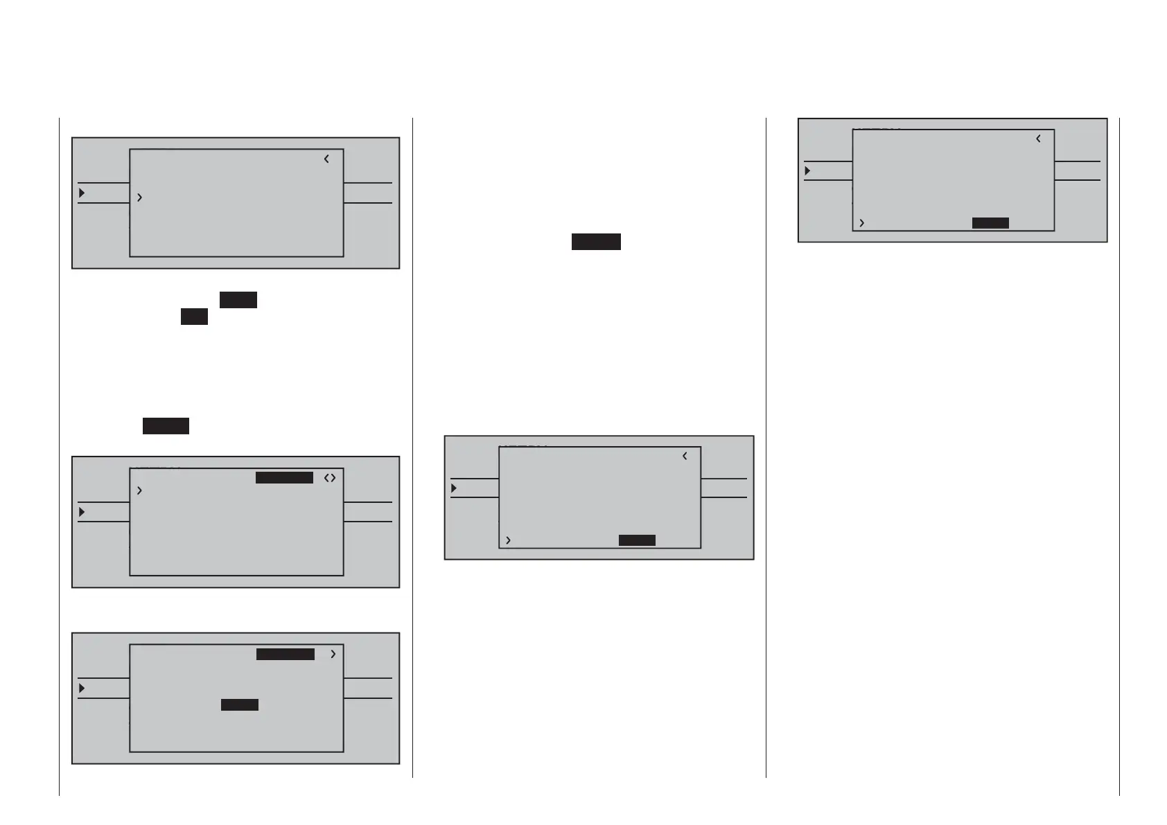
shown as "normal" again:
TELEMETRY
SETTING & DATAVIEW
SENSOR SELECT
RF STATUS VIEW
VOICE TRIGGER
TELEMETRI RCV
BIND. 1
RX SERVO TEST
ALL–MIN : 1000sec
ALL–MAX : 2000sec
ALARM VOLT : 3.8V
ALARM TEMP–:–10°C
ALARM TEMP+: 70°C
CH OUT TYPE:ONCE
TEST : START
To stop the servo test, reactivate the entry fi eld as
described above, select
STOP and confi rm this
selection with the
SET key of the right touch pad.
ALARM VOLT (receiver undervoltage warning)
The receiver voltage is monitored through ALARM
VOLT. The interval can be adjusted between 3.0 and
6.0 Volt. If the set alarm threshold is undercut, an
acoustic signal is issued (interval peep tone long/
short) and "
VOLT.E" blinks in the top right of all »RX
…« displays:
TELEMETRY
SETTING & DATAVIEW
SENSOR SELECT
RF STATUS VIEW
VOICE TRIGGER
TELEMETRI RCV
BIND. 1
RX SERVO
REVERSE : OFF
CENTER : 1500sec
TRIM : –000sec
TRAVEL– : 150%
OUTPUT CH: 01
TRAVEL+ : 150%
PERIOD : 20msec
VOLT.E
The parameter "R-VOLT" is also represented
inversely in the »RX DATAVIEW« display:
TELEMETRY
SETTING & DATAVIEW
SENSOR SELECT
RF STATUS VIEW
VOICE TRIGGER
TELEMETRI RCV
BIND. 1
VOLT.E
S–STR100% R–TEM.+28°C
L PACK TIME 00010msec
L.R-VOLT:03.5V
S–QUA100%S–dBM–030dBM
SENSOR1 :00.0V 00°C
SENSOR2 :00.0V 00°C
R-VOLT :03.7V
RX DATAVIEW VOLT.E
ALARM TEMP +/- (recommended temperature
monitoring)
These two options monitor the receiver temperature.
A lower threshold "ALARM TEMP-" (-20 … +10 °C) and
an upper threshold "ALARM TEMP+" (50 … 80 °C)
can be programmed. When these specifi cations are
exceeded or undercut, an acoustic signal (continuous
peep tone) sounds and "
TEMP.E" appears in the top
right of all receiver displays. In addition, the parameter
"R-TEM" is shown inversely on the "»RX DATAVIEW«"
display page.
Make sure that your receiver remains within the
permissible temperature range during all fl ight
conditions (ideally between -10 and 55 °C).
CH OUTPUT TYPE (connection type)
Here you select how the receiver outputs are
controlled.
• ONCE
TELEMETRY
SETTING & DATAVIEW
SENSOR SELECT
RF STATUS VIEW
VOICE TRIGGER
TELEMETRI RCV
BIND. 1
VOLT.E
RX SERVO TEST
ALL–MIN : 1000sec
ALL–MAX : 2000sec
ALARM VOLT : 3.8V
ALARM TEMP–:–10°C
ALARM TEMP+: 70°C
TEST : START
CH OUT TYPE:ONCE
The servo connections of the receiver are
controlled successively. This is recommended for
analog servos.
This setting automatically operates servos in a
20 ms cycle – or in a 30 ms cycle for a 12 channel
receiver (order no. 33512) – , regardless of what is
set or displayed in the "PERIOD" line of the »RX
SERVO« screen!
• SAME
TELEMETRY
SETTING & DATAVIEW
SENSOR SELECT
RF STATUS VIEW
VOICE TRIGGER
TELEMETRI RCV
BIND. 1
VOLT.E
RX SERVO TEST
ALL–MIN : 1000sec
ALL–MAX : 2000sec
ALARM VOLT : 3.8V
ALARM TEMP–:–10°C
ALARM TEMP+: 70°C
TEST : START
CH OUT TYPE:SAME
The servo connections of the receiver are
controlled in parallel in blocks of four. This
means channels 1 through 4, 5 through 8 and
9 through 12 each receive the control signals
simultaneously.
This is recommended for digital servos when
multiple servos are used for one function (e.g.
aileron), so that the servos can run absolutely
synchronized.
When only using digital servos, we recommend
setting the "PERIOD" line of the »RX SERVO« to
10 ms in order to be able to utilize the fast reaction
of digital servos. With the use of analog servos or
in mixer mode, "20 ms" must be selected!
With this setting, pay particular attention to the
suffi cient dimensioning of the receiver current
supply. Since up to four servos can always
operate simultaneously, the requirement is higher.
• SUMO (sum signal OUT)
A HoTT receiver confi gured as SUMO permanently
generates a so-called sum signal from the control
signals of all of its control channels and provides
this by default to the accompanying GR-32 DUAL
receiver on servo connection 8.
On receivers whose display shows "SUMO" at the
top right, an additional two-digit number appears …

 Loading...


