247
Detail program description - Multi-channel
MIX active/phase MIX-only channel
Dual mixer
Fail-safe adjust
Teacher / pupil Tx. output swap
Profi trim
Trim memory
Telemetry Channel sequence
Multichannel Ring limiter
MIX-only channel Dual mixer
Swashplate mixer Fail-safe adjust
Teacher / pupil Tx. output swap
Profi trim
Trim memory
Telemetry Channel sequence
Multichannel Ring limiter
… then open this menu option with a brief tap on the
center
SET key of the right touch pad.
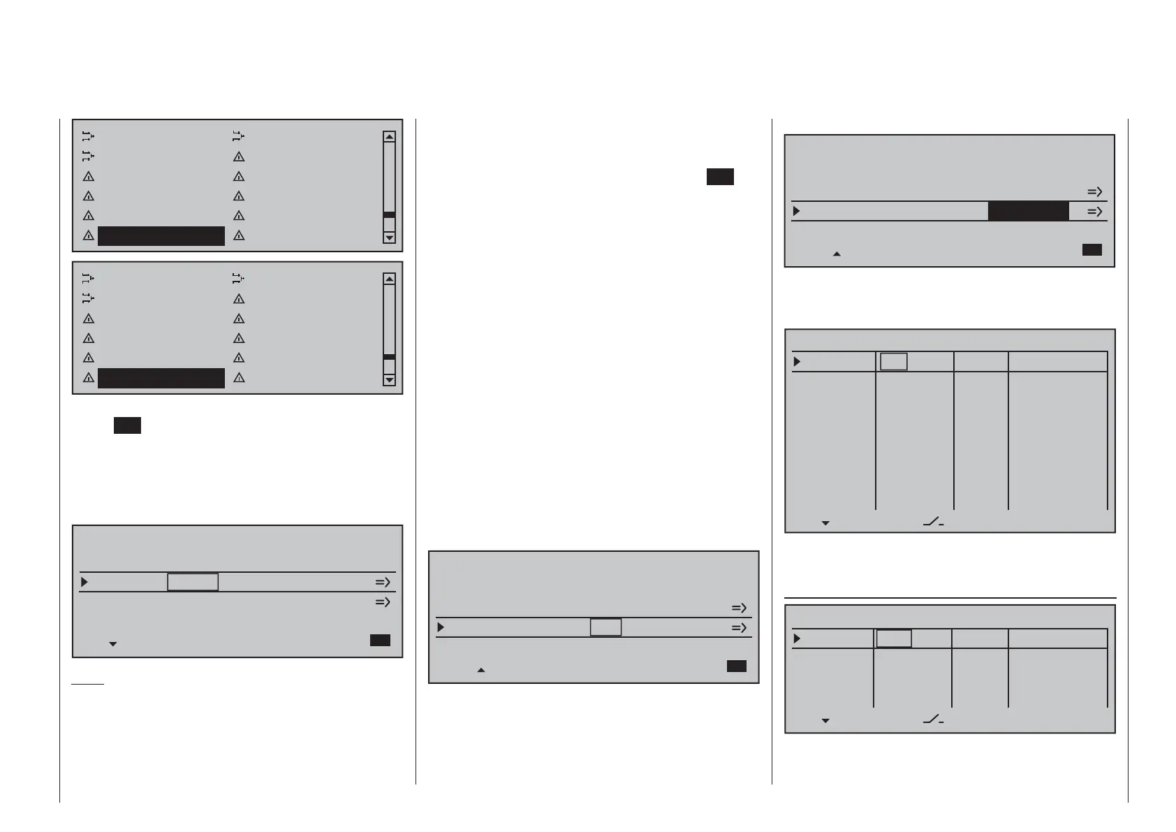
Here, in the second column from the left, each of the
two multi-channel functions can be activated ("ACT")
or deactivated ("INACT") as desired and in the third
column the given function can be assigned to one of
the transmitter channels, C5 through C8, in a list.
MULTICHANNEL
MULTIC1
MULTIC2
INACT
INACT
C5
C6
SET SEL
MULTIC 4CH
MULTIC 4CH
SEL
Note:
When a changeover is made to the »Servo display«
or if »Servo adjustment« is used to select the
"-travel+" or "-lim +" columns for these previously set
channels, their respective cells will fl ash to indicate
that these channels have been activated in the
»Multichannel« menu. The preset values of 100 % or
150 % should not be changed.
Prior to channel selection, please observe the
following notices:
Switch to the 1. "SETTINGS/DISPLAYS" line of the
»Telemetry« menu and tap on the center
SET key
of the right touch pad:
on the "RX SERVO" page, select the "20 msec" •
setting in the last line "PERIOD", see page
231.
On the "RX SERVO TEST" display page, •
select the "SAME" option for the last line "CH
OUT TYPE", see page 238.
The control channel used may not be used as an 2.
input nor as an output channel for any mixer! For
example, if C5 is selected, be sure that the "Aile/
fl aps" line of the »Model type« menu is preset
to "1AIL" or that the "Swashplate type" line of the
»Helicopter type« menu is preset to "1 servo".
The channel settings intended for NAUTIC control 3.
channel purposes in the »Control adjust« and
»Servo adjustment« menus are to be left as
they are or reset back to their original settings.
Do not assign any transmitter control or switch to
the respective input either. Also be sure that the
servo's direction of rotation is not reversed. Leave
the servo middle at 0%.
MULTICHANNEL
MULTIC1
MULTIC2
ACT
ACT
C5
C6
SET SEL
MULTIC 4CH
MULTIC 4CH
SEL
In the next column to the right, make a separate
channel count specifi cation for each of the two multi-
channels; "MULTIC 4C." for the NAUTIC-Multi-Prop
mini decoder, order no. 4142.N or "MULTIC 8C."
for the NAUTIC-Expert switching module, order no.
4159.
MULTICHANNEL
MULTIC1
MULTIC2
ACT
ACT
C5
C6
SET SEL
MULTIC 4CH
SEL
MULTIC 8CH
Afterward, use the right arrow symbol at the bottom
line's right end to switch over to the second page of
settings for the »Multichannel« menu:
MULTICH 2
–––
SEL Offset
Input 1
Input 2
Input 3
Input 4
Input 5
Input 6
Input 7
Input 8
fr
fr
fr
fr
fr
fr
fr
fr
–––
–––
–––
–––
–––
–––
–––
+100%
+100%
+100%
+100%
+100%
+100%
+100%
+100%
0%
0%
0%
0%
+100%
+100%
+100%
+100%
+100%
+100%
+100%
+100%
0%
0%
0%
0%
– travel +
This menu page is now used for making individual
settings for "MULTICH 1" and "MULTICH 2".
Column 2, "Control"
–––
SEL Offset
Input 1
Input 2
Input 3
Input 4
fr
fr
fr
–––
–––
–––
+100%
+100%
+100%
+100%
+100%
+100%
+100%
+100%
0%
0%
0%
0%
– travel+
fr
MULTICH 2
Use the arrow keys to move to the column over SEL.

 Loading...


