248 Detail program description - Multi-channel
and then connected as necessary.)
If a Nautic-Expert switching module (order no. 4159) is
present, the assigned proportional control will function
like a switch when it is put near its limit position.
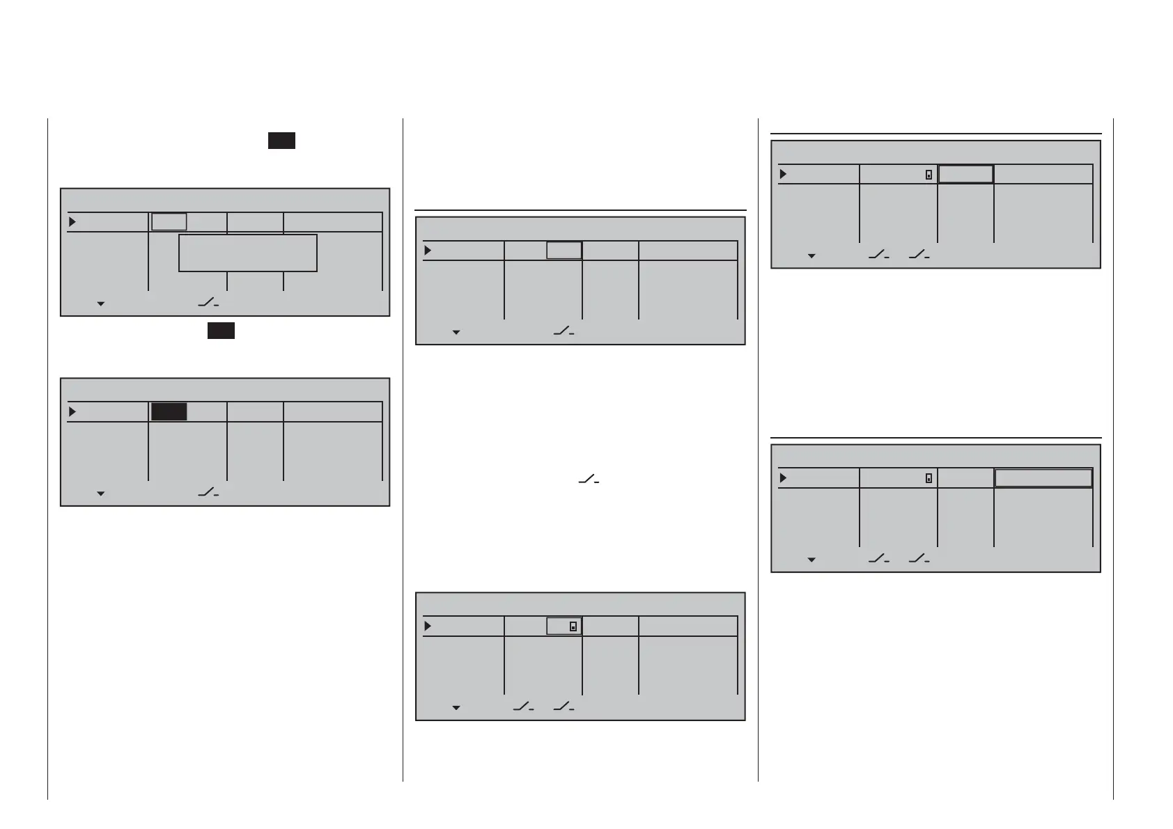
Column 3, "Switch"
–––
SEL Offset
Input 1
Input 2
Input 3
Input 4
fr
fr
fr
–––
–––
–––
+100%
+100%
+100%
+100%
+100%
+100%
+100%
+100%
0%
0%
0%
0%
– travel +
fr
MULTICH 2
This column is used to assign each of the inputs
used, 1 through 8 (maximum), to any switch available
on the transmitter. These assignments are done
as described in the section "Assigning transmitter
controls, switches and control switches" on page 56:
Any controls which were previously assigned in the
second column will be erased. In this case, instead
of SEL, the switch symbol
will be displayed at the
bottom of the 2nd column such that now a second
"normal" switch, or even a transmitter control switch,
logical switch, … can be assigned as needed from
the group of "expanded switches". In general it is
suffi cient to assign a simple switch or transmitter
control.
–––
Offset
Input 1
Input 2
Input 3
Input 4
fr
fr
fr
–––
–––
–––
+100%
+100%
+100%
+100%
+100%
+100%
+100%
+100%
0%
0%
0%
0%
– travel +
3
MULTICH 2
Column 3, "Offset"
–––
Offset
Input 1
Input 2
Input 3
Input 4
fr
fr
fr
–––
–––
–––
+100%
+100%
+100%
+100%
+100%
+100%
+100%
+100%
0%
0%
0%
0%
– travel +
3
MULTICH 2
The control center for the given control, i.e. its zero
point, can be changed in this column. The adjustment
range lies between -100 % and +100 %.
Simultaneously tapping on the cd or ef keys of
the right touch pad (CLEAR) will reset the value
displayed in inverse video back to its "0 %" value.
Leave the offset setting at 0 % while making switch
assignments.
Column 3, "–travel+"
–––
offset
INPUT 1
INPUT 2
INPUT 3
INPUT 4
fr
fr
fr
–––
–––
–––
+100%
+100%
+100%
+100%
+100%
+100%
+100%
+100%
0%
0%
0%
0%
– travel +
3
MULTICH 2
Finally, transmitter control travel is set for both sides
in the rightmost column "-travel+". The range for this
lies between -100 % and +100 %. To accomplish this,
push or turn the respective transmitter control in the
given direction. This will set the "travel" for each given
direction individually.
If the assignment is for a switch, leave the setting at
the default value of 100 %.
After completing the activation of transmitter control
assignment by tapping the center
SET key of the right
touch pad , the message shown below will appear in
the display:
–––
SEL Offset
Input 1
Input 2
Input 3
Input 4
fr
fr
fr
–––
–––
–––
+100%
+100%
+100%
+100%
+100%
+100%
+100%
+100%
0%
0%
0%
0%
– travel +
fr
MULTICH 2
Move desired
control adj.
Alternatively, the center SET key of the right touch
pad can be tapped for a second time while this
message is on display:
–––
SEL Offset
Input 1
Input 2
Input 3
Input 4
fr
fr
fr
–––
–––
–––
+100%
+100%
+100%
+100%
+100%
+100%
+100%
+100%
0%
0%
0%
0%
– travel +
fr
MULTICH 2
Now the desired transmitter control can be selected
with the selection keys on the left or right touch pad.
If the selected control has an assignment, it can be
disconnected from a transmitter control switching its
fi eld to "fr".:
transmitter control 1 … 4 (CH 1 …4)•
slider control 1 … 3 in the middle of the console •
(SR1 … 3)
depressible, roller-shaped proportional speed •
control (DG1 … 5)
side proportional control control (SD1 and SD2)•
(Function inputs "UV1" through "UV8", which are also
in the selection list, can be selected at a later time

 Loading...


