294 Programming examples - Using fl ight phases
The mixing direction is to be selected
so that all fl aps are defl ected downward
with the elevator pulled up and defl ected
upward with the elevator pushed down (=
hydroplane). The mix proportion is normally
in the low double-digit range.
Now, within the »Wing mixers« menu, switch to the
"Brake settings" …
Elevat. curve
BRAKE SETTINGS
Normal
Crow
AI
+22%
WK2
0%
FL
+66%
Diff. reduct.
WK2
+33%
0%
+33%
Note:
The "Brake settings" menu is switched "off" if: "Motor
on C1 forward / back" in the »Model type« menu
(page 94) AND the "Motor" column of the »Phase
settings« menu, (page 142) are set to "yes" for the
currently active fl ight phase. Change the fl ight phase,
if applicable.
Crow Further above in this text section, the C1
joystick was set for brake fl ap steering.
In this line you determine the share
with which the AI and FL should be
included on actuation of C1 in the
manner that both ailerons are defl ected
"slightly" upward and both fl aps are
defl ected as far downward as possible.
Now with a simultaneous tap on the
ef keys of the left touch pad, a
change to the »Servo display« menu
can be affected for observation of servo
movements and, in particular, to ensure
that no infl uence on the fl aps takes
place above the adjusted brake offset,
e.g. +90 % and beyond to the throw
limit of the C1 control ("Idle travel" of
the C1 joystick).
Diff. reduct. The value previously entered into
the aileron differentiation line should
also be entered in this "Differentiation
reduction" line to fade this out during
braking.
Elevat. curve
This line is used for the entry of any
correction factor that may be required
for the elevator, see page 174.
Insofar as necessary, again check all fl ap throws and,
by way of the »Servo adjustment« menu, adjust the
servo center, the servo travel and the travel limit.
It may also be time to start the initial fl ight testing,
insofar as all global settings – that is to say, all fl ight-
phase independent settings – are completed.
Two additional fl ight phases are now to be set
up below, each of which requires a somewhat
different fl ap position.
Therefore, switch to the menu …
»Phase settings« (page 142)
… and activate the assignment of phase names in
the "Name" column with a brief tap on the center
SET
key of the right touch pad:
Phase 1
Phase 2
Phase 3
Phase 4
Phase 5
0.1s
0.1s
0.1s
0.1s
0.1s
Name
Fl.ph.Tim. Sw. time
–
–
–
–
¾
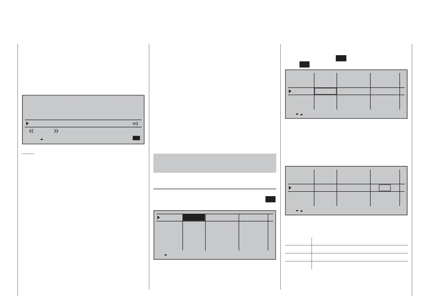
Now give Phase 1 – the "Normal phase" – that is also
the phase which includes the previous settings, the
name "Normal", which you select from a list with the
selection keys.
Phase 2 is given the name "Thermal" and Phase 3 is
given the name "Speed". Now conclude the entries
with a brief tap on the
ESC key of the left touch pad
or the
SET key of the right touch pad:
Phase 1
Phase 2
Phase 3
Phase 4
Phase 5
0.1s
0.1s
0.1s
0.1s
0.1s
Name
Fl.ph.Tim. SW. time
–
–
–
–
¾
Normal
Thermal
Speed
Now move the marker frame beyond the "Fl.ph.Tim"
column to the right into the column "Sw. time" and set
a "switching time" from any other phase into the given
phase in order to avoid an abrupt phase change; in
other words to avoid erratic changes of fl ap positions.
Now try out different switching times. In this example
we have specifi ed 1 s in each case:
Phase 1
Phase 2
Phase 3
Phase 4
Phase 5
1.0s
1.0s
1.0s
0.1s
0.1s
Name
Fl.ph.tim. Sw. time
–
–
–
–
¾
Normal
Thermal
Speed
Whether or not one of the phases 1 … 8 currently has
an assigned switch and the state of the switch can be
seen in the "status" column at the far right.
Symbol Meaning
– No switch assigned
+ Phase can be called via switch
¾
Indicates the currently active phase
Since, except for phase 1, all other phases are still
designated with a "-" symbol, now switch in the
menu to …

 Loading...


