305
Programming examples - F3A model
After the model is test-fl own and trimmed, we
recommend reducing trim travel for the elevator and
ailerons The model has signifi cantly less of a reaction
to a movement of the trim wheel. "Over-trimming"
can be avoided, because with full trim travel, under
certain circumstances, the movement by just one
trimming step can have too strong of an effect:
Therefore, the model which previously pulled slightly
to the left, hangs somewhat to the right after the
trimming. For this purpose, switch to the menu …
»Stick mode« (page 104)
… and reduce the number of trim steps in the "Tr.s
tep" column appropriately:
global
Channel 1
Aileron
Elevator
Rudder
Tr im
0.0s
Tr.s tep – time +
global
0.0s
0.0s
global
0.0s
0.0s
0.0s
0.0s
0.0s
4
4
4
Phase
2
It may also be necessary to assign appropriate
operating elements and inputs for other model
features, e.g. retractable landing gear, fuel-mix, etc.
Make these assignments with the …
»Control adjust« (page 108)
… menu where a specifi c input can be assigned to an
operating element, for example, the landing gear can
be assigned to an ON/OFF switch on Input 6 and the
fuel-mix can be assigned to one of the proportional
sliders in the middle console, e.g. the center slider
to Input 7. However, since it involves fl ight-phase
independent settings, leave the standard default "GL"
in the "Type" column:
+33%
+33%
+33%
Aileron
Elevator
Rudder
DUAL
–––
SEL
–––
–––
–––
100%
100%
100%
EXPO
SEL
Normal
–––
(Some experts even use up to a +60 % exponential
ratio.)
Since (some) combustion motors do not react linearly
to movements of the throttle joystick, through the
menu …
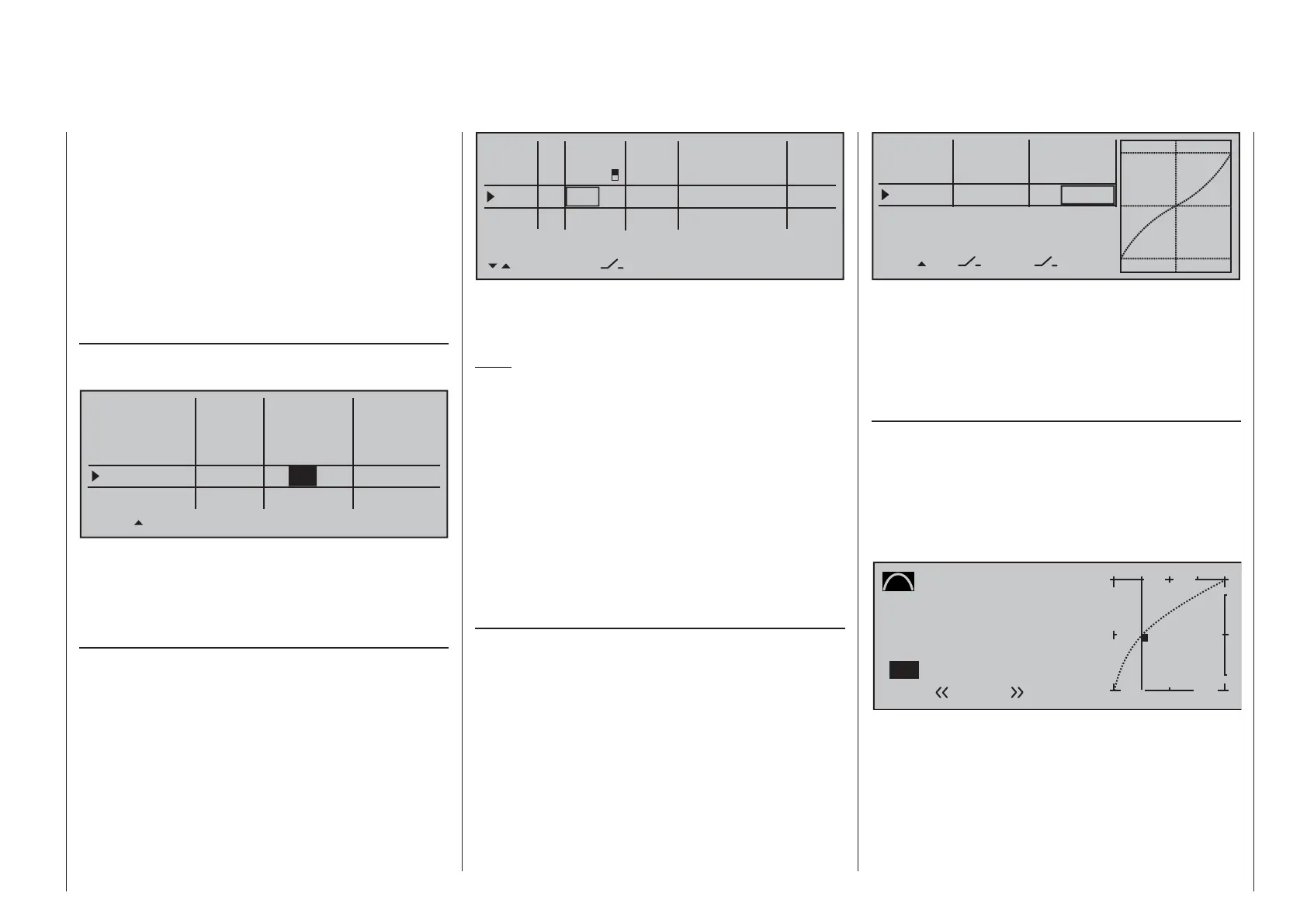
»Channel 1 curve« (page 128)
… a "bowed" or, in other words, non-linear throttle
curve can be set. Four-cycle motors with Roots
pumps, in particular, such as OS Max FS 120, require
a steep ascension of the curve in the lower speed
range. However, the corresponding values must be
adapted. The C1 control curve for the motor could
appear as follows:
Channel 1 C U R V E
Curve
Point
Output
Input –50%
0%
1
+
–
100
¼ O U T P U T
0%
Normal
on
1
Only three interpolation points, "L" at -100 %, "H" at
+100 % and "1" at -50 % give the control travel the
rounded curve above.
Basic procedure:
Move the C1 joystick and, along with it the vertical •
line in the graph display, toward idle to about
0%
+100%I5
I6
I7
I8
Typ
+100%
0.0 0.0
– travel + –time+
0%
+100%
+100%
0.0 0.0
0%
+100%
+100%
0.0 0.0
0%
+100%
+100%
0.0 0.0
GL
GL
GL
fr
Sl2
---
---
---
---
offset
GL fr
Normal
2
SEL
The control travel of the operating elements must be
adapted and can also be reversed with a negative
travel setting.
Note:
A delay time can be specifi ed for raising and lowering
the retractable landing gear, however, such a time
delay is not effective for landing gear servo C 713 MG,
order no. 3887.
F3A models fl y comparatively fast and thus react
"harshly" to the control movements of the servos.
However, since small control movements and
corrections are not optically perceptible, because this
results in inevitable point deductions in competition,
we recommend setting an exponential control
characteristic of the joystick. For this purpose,
switch to the menu …
»Dual Rate / Expo« (page 120)
Experience has shown positive results with values of
approx. + 30 % on the ailerons, elevator and rudders,
which you set in the right column with the selection
keys. In order to be able to control the F3A model to
run smoothly and cleanly:

 Loading...


