314 Programming examples - Helicopter models
If you switch from this graphic to the autorotation
phase for testing purposes, the following appears
instead of the accustomed representation:
off
C1 Throttle
Autorot
That means that this mixer is switched off and the
throttle servo is switched to a fi xed value, which can
be adjusted as follows:
Return to the menu list with a tap on the
ESC key. As
long as you are still in the autorotation phase, new
sub-menus are listed; specifi cally:
Pitch
–90%
Tail rot. offset AR
0%
Throttle position AR
Gyro suppression
0%
Gyro offset 0%
SEL
Autorot
The line "Thr. setting AR" is important. Enter the value
to the right, depending on servo direction, to either
approximately +125 % or -125 %.
Pitch
–125%
Tail rot. offset AR
0%
Throttle position AR
Gyro suppression
0%
Gyro offset 0%
SEL
Autorot
In doing so, the motor is safely switched off in the
autorotation phase (in case of emergency). Later,
when you have gained enough experience to practice
the autorotation fl ight, a more stable idle can be
entered here.
Adjustment notice for electric helicopters:
Since the motor must also be shut off for electrically
powered helicopters in case of an emergency, this
setting is adopted without change.
The further sub-menus are not important at the
moment. By switching off "autorotation", it returns to
the fi rst menu list.
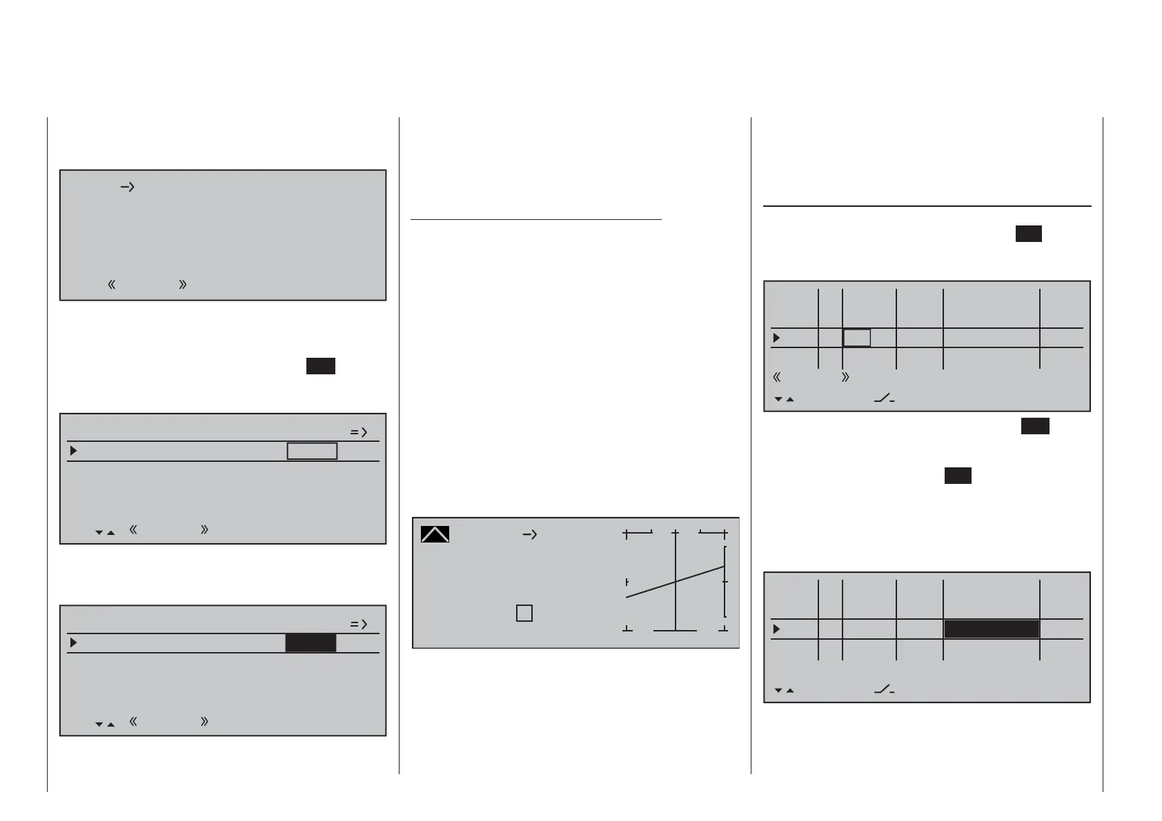
Select the "Channel 1 ¼ Tail rot." settings page
in order to set static torque compensation for the
tail rotor. In this case, also work with a maximum of
three interpolation points; everything else is reserved
for the experienced pilot. Do this by changing the
heading-lock systems from their intended uniform
pre-setting of 0 % at point "L" (minimum pitch) to
-30 % and at the opposite end, at point "H" to +30 %
(maximum pitch). These values may have to be
corrected in fl ight. It may also be necessary to set
point "1" in the middle.
Channel 1
Curve
off Point
Output
Input 0%
0%
?
+
–
100
¼ O U T P U T
0%
Tail rot.
Now, for testing purposes, switch back to the
autorotation phase. Here the setting is also
deactivated; the tail servo no longer reacts to pitch
movements (no torque usually arises when the main
rotor is not powered). All additional interpolation
points are not currently of importance yet.
If, contrary to the default setting, the gyro has a
transmitter-side sensitivity setting, another free
proportional control will be needed. This can be
assigned in the …
»Control adjust« (page 112 … 119)
… menu to "Gyr7" input. Activate the control
assignment with a brief tap on the center
SET key of
the right touch pad then move the selected control
until its control number appears in the display:
0%
I5 +88%
Thr6
Gyr7
I8
Typ
+111%
– travel + –time+
0%
+100%
+100%
0.0 0.0
0%
+100%
+100%
0.0 0.0
0%
+100%
+100%
0.0 0.0
GL
GL
GL
fr
Sl1
fr
---
---
---
offset
GL
Normal
0.0 0.0
SET
fr ---
Conclude this entry with a brief tap on the ESC key of
the left touch pad then change to the column "- travel
+" with the f selection key of the left or right touch
pad. After a tap on the center
SET key of the right
touch pad, the gyro's maximum sensitivity can be set
in the value fi eld displayed in inverse video, e.g. to
50 %. To this end, move the selected control into its
middle position or, if applicable also to the side, such
that only one value fi eld is displayed in inverse video:
0%
I5 +88%
Thr6
Gyr7
I8
Typ
+111%
– travel + –time+
0%
+100%
+100%
0.0 0.0
0%
0.0 0.0
0%
+100%
+100%
0.0 0.0
GL
GL
GL
fr
Sl1
fr
---
---
---
offset
GL
Normal
0.0 0.0
SET
fr ---
+50%
+50%
This produces a fi xed value for as long as the control
remains at the right limit position. The correct value
must be adjusted in fl ight.

 Loading...


