38 Transmitter description - Telemetry data display
SENSOR 1
0.0V
0°C
SENSOR 1
If attached, this display depicts currently measured
voltage and temperature from a temperature/voltage
sensor, order no. 33612 or 33613, connected
to "T(EMP)1" of the General-Engine module
(order no. 33610) or the General-Air module (order
no. 33611).
SENSOR 2
0.0V
0°C
SENSOR 2
If attached, this display depicts currently measured
voltage and temperature from a temperature/voltage
sensor, order no. 33612 or 33613, connected to
"T(EMP)2" of the General-Engine module (order
no. 33610) or the General-Air module (order no.
33611).
Rotary speed sensor
U/min
0
0
0
If attached, this display depicts the measured
rotary speed of a speed sensor (order no. 33615
or 33616) attached to a General-Engine module
(order no. 33610) or a General-Air module (order no.
33611).
Note:
The appropriate blade count must fi rst be set in the
module's telemetry menu before the correct speed
can be displayed.
Vario
0.0
0
m
m
s
If attached, this display will depict the altitude (in
m) relative to location, starting location as well as
the current rate of ascent/descent (in m/s) data
originating from a Vario integrated into a General-
Engine module (order no. 33610) or General-Air
module (order no. 33611).
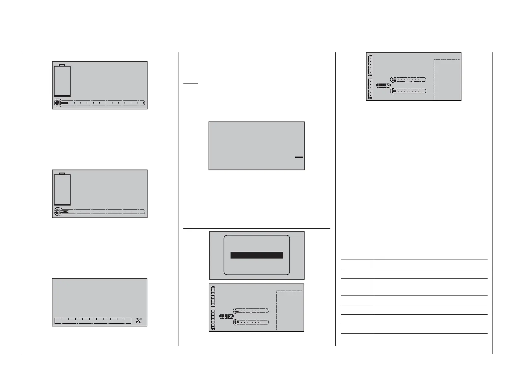
ELECTRIC AIR MODULE
RX–S QUA: 100%
RX–S ST : 100%
TX–dBm: 33dBm
RX–dBm: 33dBm
RX–SPG.:4.8 TMP
V–PACK: 10ms
CH OUTPUT TYPE:ONCE
RECEIVER
GENERAL
ELECT. AIR
VARIO
GPS
0.0V 0m/3s
BAT1 0m/1s
BAT2
0.0V T2 0°C
T1 0°C
0
1L0.00
2L0.00
3L0.00
4L0.00
5L0.00
6L0.00
ALT 0m
7L0.00
0.0V 0A
0.0V 0m/3s
BAT1 0m/1s
BAT2
0.0V T2 0°C
T1 0°C
0
1H0.00
2H0.00
3H0.00
4H0.00
5H0.00
6H0.00
ALT 0m
7H0.00
0.0V 0A
If attached to the receiver, this display will depict the
data acquired by an Electric-Air module, order no.
33620. More details about this module can be found
in the appendix or in Internet at www.graupner.de in
the web page for the given product.
Depending on how this module is equipped with
sensors, this screen can permanently display the
data shown in the adjacent table.
The current voltage of up to two batteries (BAT1 and
BAT2), up to two temperature measurements (T1
and T2), current altitude with respect to the starting
location, the model's ascent/decent rate in m/1 s and
m/3 s and, in the middle of the screen, the current
draw currently being taken from a power source.
Along the right edge of the screen is a table of
alternating values for cell voltages at balancer
connections (L) or voltages for up to 7 attached
battery cell packs (H).
The displayed items are as follows:
Value Explanation
V current voltage
A current current
BAT1 /
BAT2
battery 1 or 2
ALT current altitude
m/1 s m/1 s ascent/decent rate
m/3 s m/3 s ascent/decent rate
T1 / T2 temperature of sensor 1 or 2

 Loading...


