91
Detail program description - Base setup models | Winged models
Marking
BASIC SETTING,MODEL
SET SET
–––
Autorotation
Autorot. C1-Pos.
0%
–––
SEL
STO
Thr. CutOff
+100%
–125%
8
Marker key
–––
When activated, the "Marker key" will place a marker
in the "Pitch" curve, as well as in the "Channel 1 ¼
Throttle" and "Channel 1 ¼ Tail rotor" mixer curves
of the »Helicopter mixer« menu, to mark the current
pitch joystick position of the pitch joystick and it takes
on the form of a vertical dashed line. This marker
is helpful for setting curve points at the right places
during fl ight testing, e.g. the hovering point
One of the two standard momentary contact switches
mounted into the switch panels should be the
preferred choice of switch assignment.
Example:
The hovering point is to be placed at the midpoint of
the throttle/pitch joystick for the «Hover» fl ight phase
but it is found to be still located above control middle
during fl ight testing. Press the switch in this position
and, after the landing, examine, for example, the
Pitch curve in the »Helicopter mixer« menu, page
176.
Pitch
Curve
off Point
Output
Input –30%
–30%
?
+
–
100
¼ O U T P U T
The continuous vertical line shows the joystick's
current position. Its position in this example lies at
-30 % (= input) of control travel and, because of its
(still) linear control curve, produces an output signal
which is also -30 % (= output).
On the other hand, the dashed vertical line represents
the joystick position at which the marker switch was
pushed.
Move the joystick to this marker line to read the input
and output values for the found hovering point. The
marker points of the other two mixer curves are read
similarly. Now these three curves can be alternately
modifi ed as necessary in order to correct the hovering
point. Curve point "1" in this simple example can be
raised at the curve's midpoint to the output value that
was determined to be the hovering point in the Pitch
graph.
Power-on warning
BASIC SETTING,MODEL
SET SET
–––
Autorot. C1-Pos.
0%
–––
SEL
STO
Thr. CutOff
+100%
–125%
8
Marker key
–––
Power on warning
When a switch, a control switch or a logical switch is
assigned in this line, as described on page 56 in the
section "Assigning transmitter controls, switches and
control switches", the respective switch or control
position will be polled when the transmitter is switched
on and an appropriate warning will be blended into the
basic display under some conditions. In combination
with logical switches, almost any switch setting can be
called up for transmitter switch on.
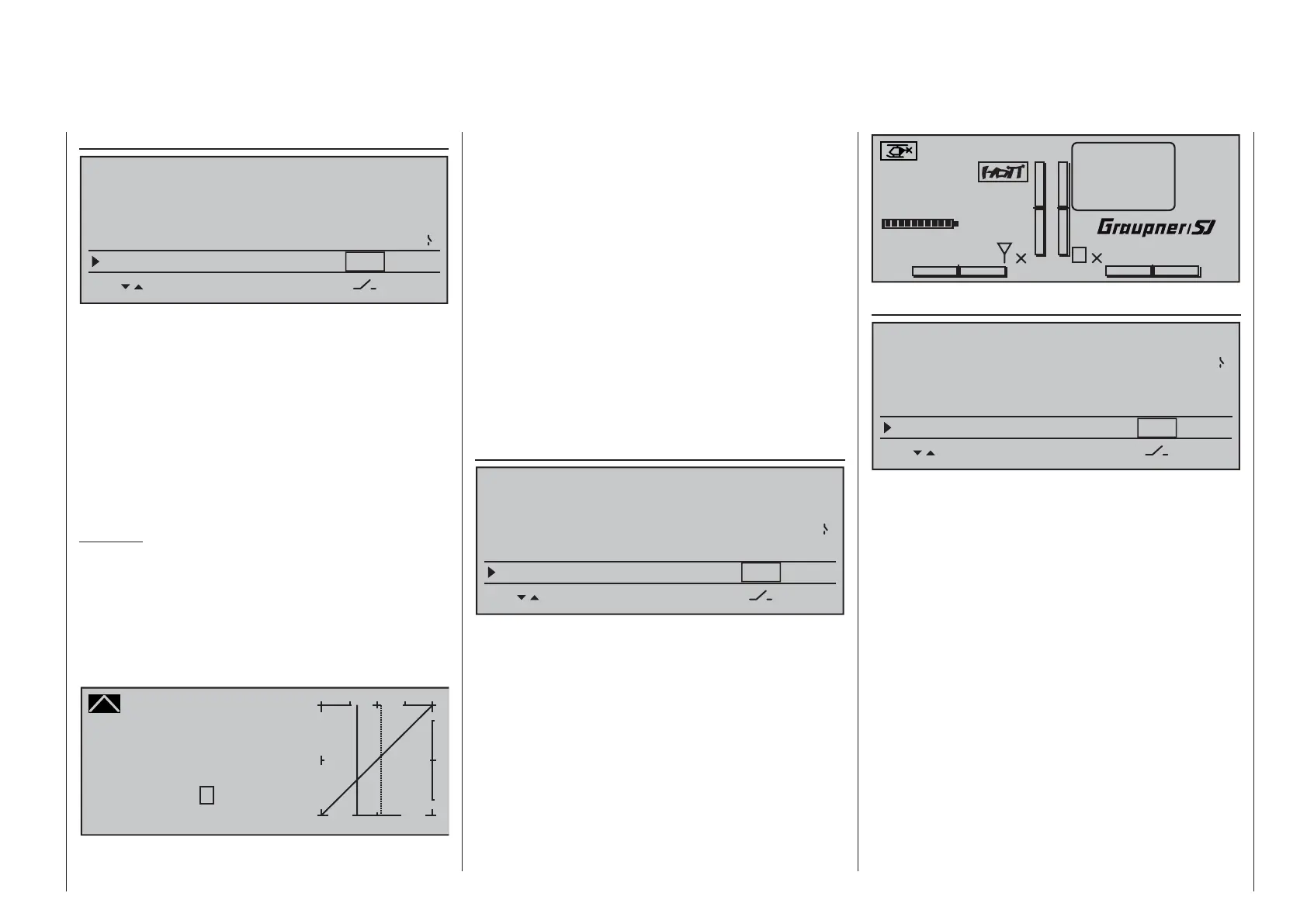
#02
0:00h
Stoppuhr
Flugzeit
K78
0:00.0
4.1V
0:00.0
00
0
0
00:00h
M
V
!Warning!
Starlet
H-J Sandbrunner
Auto trim
BASIC SETTING,MODEL
SET SET
–––
–––
SEL
STO
Thr. CutOff
+100%
–125% 8
Marker key
–––
Power on warning
Auto trim
The "Auto trim" option makes it possible to trim a
model quickly and without complications, e.g. in the
context of a fi rst-fl ight or even after (major) repairs, etc.
Typically such test fl ights are initially fl own with
joysticks counter operated until the desired state of
fl ight is achieved. This generally involves working
the trim controls during the fl ight to "unburden" the
joysticks.
This is exactly what the "Auto trim" function is for.
After the desired fl ight attitude has been achieved via
control functions 2 … 4 (aileron, elevator and rudder),
the switch assigned to "Auto trim" – ideally one of
the standard-equipment momentary switches in the
switch panels – is to be activated ONCE. At the instant
the switch is activated, the joystick offsets from their
neutral positions will be determined and adopted
as trim values. However, this does not take place
instantaneously but rather within about 1 second.
During this period after the switch has been activated,
the joysticks should be returned to their normal
positions.