3
3 Drive or LCD mart management module (optional)
4 Serial label pull tab
5 Dedicated management connector
6 USB 2.0 connector
7 VGA connector
*: Drive types supported by the server vary by drive backplane configuration. For more information, see
"Drive backplanes."
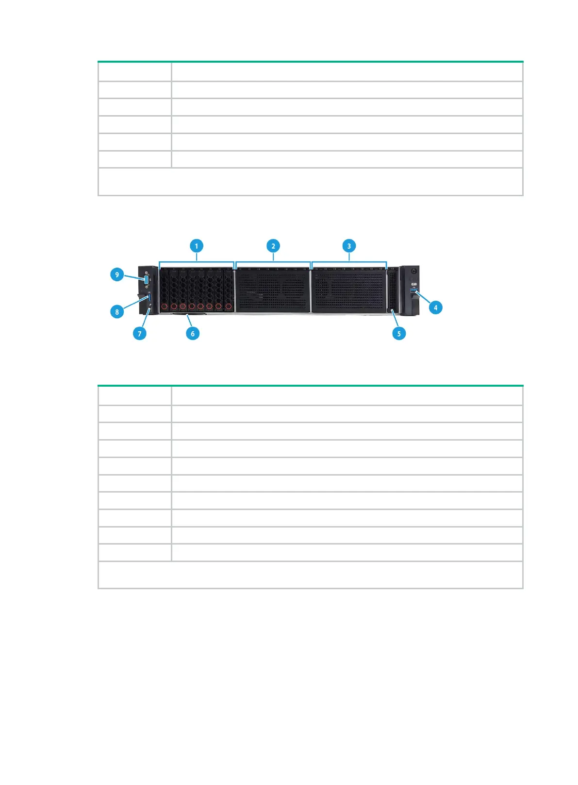
Figure 4 8SFF front panel
Table 3 8SFF front panel description
1 Bay 1: 8SFF drives (optional)*
2 Bay 2: 8SFF drives (optional)*
3 Bay 3: 8SFF drives (optional)*
4 USB 3.0 connector
5 LCD smart management module (optional)
6 Serial label pull tab
7 Dedicated management connector
8 USB 2.0 connector
*: Drive types supported by the server vary by drive backplane configuration. For more information, see
"Drive backplanes."
 Loading...


