PC Application
User’s Manual 27
this position for selecting a reference point on the display.
DC: the input signal is directly connected to the input amplifier/attenuator. Both AC and DC
voltage are measured.
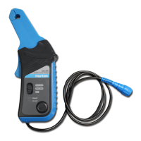
Probe Attenuation Setting
Select the attenuation factor for the probe. To check the probe attenuation setting, toggle the
probe menu to match the attenuation factor of the probe.
This setting remains in effect before you changed again. Click “Probe” in “Vertical Setting”
window to select the probe attenuation.
Note: The attenuation factor changes the vertical scale of the oscilloscope so that the
measurement results refect the actual voltage levels at the probe tip.
Bandwidth Limit
The oscilloscope is set to full bandwidth and will pass the high frequency component in the signal if
the “BW Limit” was turned off.
The oscilloscope will reject the frequency component higher than 20MHz if the “BW Limit” was
turned on.
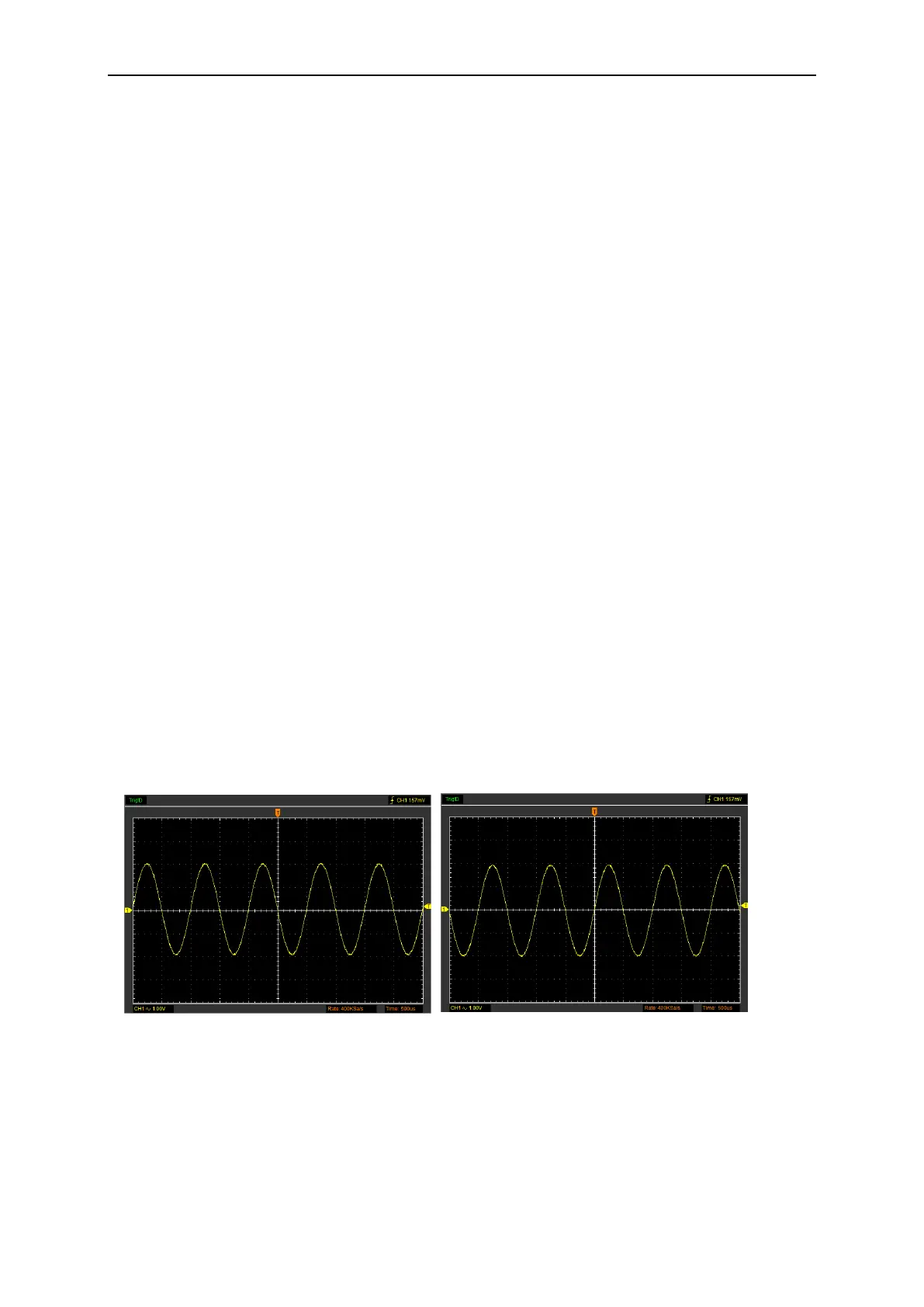
Invert
The invert function turns the displayed waveform 180 degrees, with respect to the ground level.
When the oscilloscope is triggered on the inverted signal, the trigger is also inverted.
Click “Invert” in “Vertical Setting” window.
 Loading...