Quick Start
User’s Manual 2
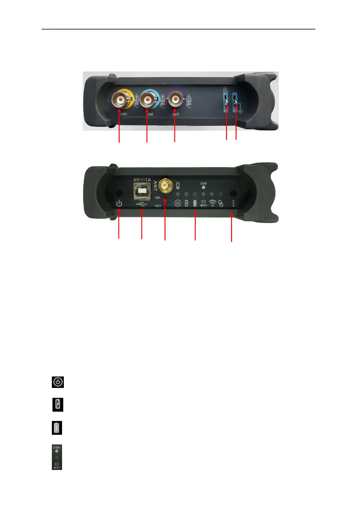
1.1 Connections and Indications
1. CH 1: Input connectors for waveform display.
2. CH 2: Input connectors for waveform display.
3. EXT.: Input connector for an external trigger source. Use the Trigger menu to select the Ext.
source.
4. CAL.: Probe compensation output.
5. GND.: Ground terminal.
6. Power Button: Power on/off button.
7. USB PORT: Connect the B-Type Plug of USB cable to this port.
8. ANT: Antenna
9. Indications
:
:
:
:

 Loading...