PC Application
User’s Manual 26
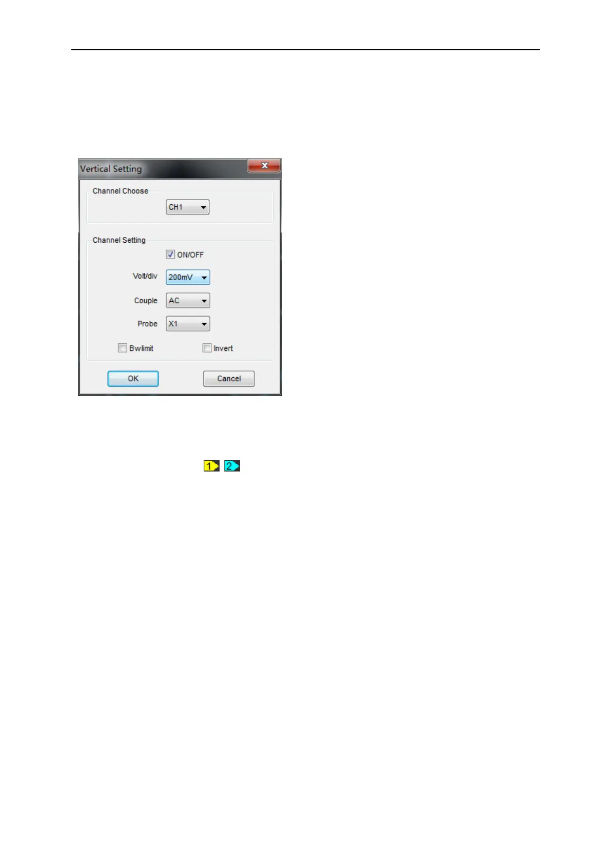
2.8 Set Vertical System
Click “Vertical” in “Setup” menu.
The following figure shows the Vertical System window. It shows the vertical parameters settings.
Also user can also set parameters in the right sidebar.
Vertical Position icon
Drag Vertical Position icon to move waveform up and down on the screen. Double click
the icon to reset the waveforms to the vertical center position on the screen.
Change Volt/Div
You can click “Volt/div” in “Vertical Setting” window to select the voltage.
You can left click and drag the mouse on the knob to change the voltage.
The signal on the screen can be enlarged or reduced vertically by adjusting the displayed voltage
per division. (V/div = voltage per division).
Set Channel Coupling
Click “Couple” in “Vertical Setup” window.
You can set the coupling to DC, AC or GND. If you set the coupling to DC, it blocks the AC
component of the input signal.
AC: the input signal is capacitive coupled to the input amplifier/attenuator. Only the AC
components are measured.
GND: the input signal is broken and the input amplifier/attenuator is connected to earth. Use
Channel Choose: User can select the channel by
clicking the Combo box.
ON/OFF: Turn on/off the channel
Volt/div: Select the channel voltage/div
Couple: Select the channel coupling
DC/AC/GND.
Probe: Set the selected one according to the
probe attenuation factor to ensure correct vertical
scale reading.
BW Limit: Reject the frequency component
higher than 20MHz.
Invert: Turn on/off the invert function.
 Loading...