Mechanical installation
T10F A0608-14.0 HBM: public 35
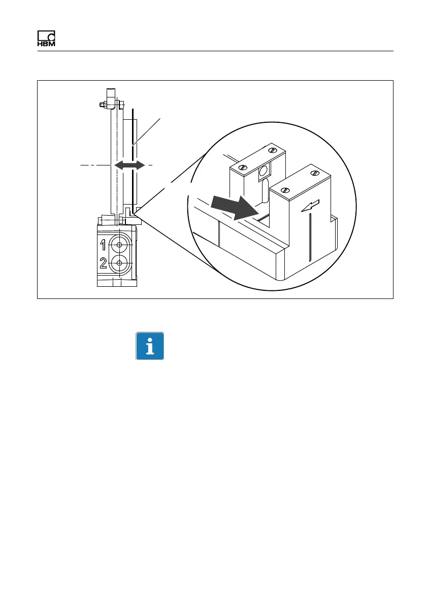
Alignment line
Slotted disc
Fig. 6.9 Position of the slotted disc in the speed sensor
Important
To attach the stator, we recommend the use of M6
screws with plain washers (width of oblong hole, 9 mm).
This size of screw guarantees the necessary travel for
alignment.
Radial alignment
The rotor axis and the optical axis of the speed sensor
must be along a line at right angles to the stator platform.
A conical machined angle (or a colored mark) in the
center of the adapter flange and a vertical marker line on
the sensor head serve as aids to orientation.