HEIDENHAIN iTNC 530 339
14.7 Compensating Workpiece Misalignment by Rotating the C Axis (Cycle
405, DIN/ISO: G405)
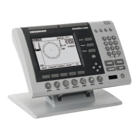
U Measuring height in the touch probe axis
Q261 (absolute): Coordinate of the ball tip
center (= touch point) in the touch probe axis in
which the measurement is to be made. Input
range -99999.9999 to 99999.9999
U Setup clearance Q320 (incremental): Additional
distance between measuring point and ball tip. Q320
is added to MP6140. Input range 0 to 99999.9999,
alternatively PREDEF
U Clearance height Q260 (absolute): Coordinate in the
touch probe axis at which no collision between touch
probe and workpiece (fixtures) can occur. Input range
-99999.9999 to 99999.9999, alternatively PREDEF
U Traversing to clearance height Q301: Definition of
how the touch probe is to move between the
measuring points:
0: Move at measuring height between measuring
points
1: Move at clearance height between measuring
points
Alternatively PREDEF
U Set to zero after alignment Q337: Definition of
whether the TNC should set the display of the C axis
to zero, or write the angular offset in column C of the
datum table:
0: Set display of C to 0
>0: Write the angular misalignment, including
algebraic sign, in the datum table. Line number =
value of Q337. If a C-axis shift is registered in the
datum table, the TNC adds the measured angular
misalignment.
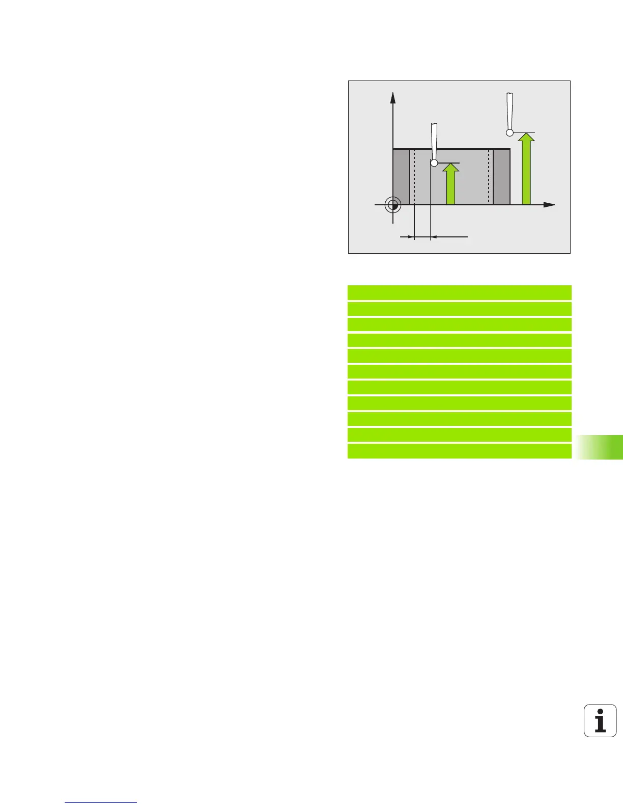
Example: NC blocks
5 TCH PROBE 405 ROT IN C AXIS
Q321=+50 ;CENTER IN 1ST AXIS
Q322=+50 ;CENTER IN 2ND AXIS
Q262=10 ;NOMINAL DIAMETER
Q325=+0 ;STARTING ANGLE
Q247=90 ;STEPPING ANGLE
Q261=-5 ;MEASURING HEIGHT
Q320=0 ;SETUP CLEARANCE
Q260=+20 ;CLEARANCE HEIGHT
Q301=0 ;MOVE TO CLEARANCE
Q337=0 ;SET TO ZERO
 Loading...