Repair Information
23
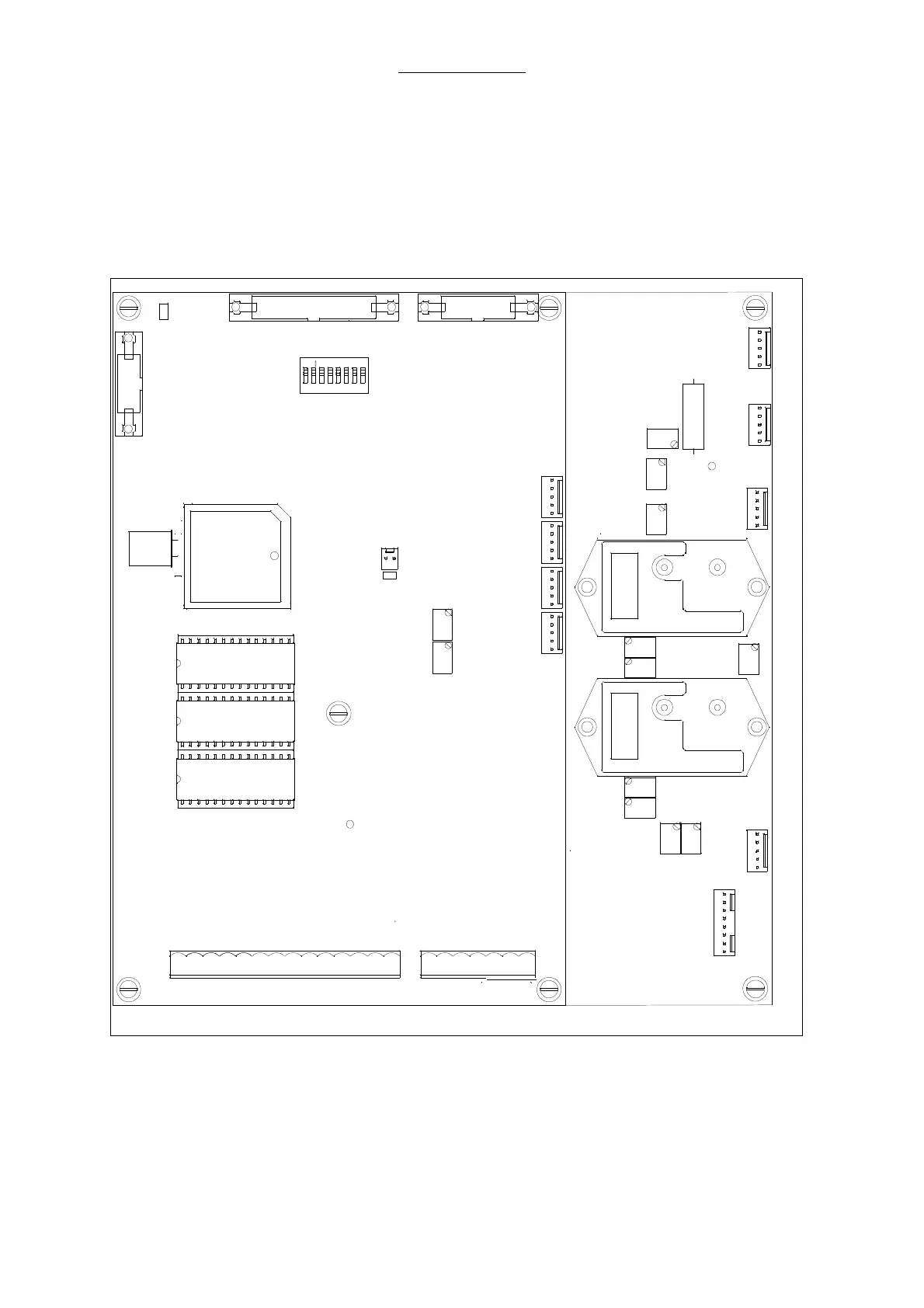
2.11 Ventilator Module 2, AVM 3-1 and AVM 3-2
Ventilator module 2 serves for the active ventilator control. Module 2 consists of two CPU boards, the
CPU board AVM3-1 with µP1 serves for a continuous validation of control actions generated by CPU
board AVM3-2 and for the communication between module 2 and module 1.
The CPU board AVM3-2 with µP2 generates all active control signals, after a validation of these
signals by µP1, AVM3-2 is enabled to operate the different active elements like the solenoid vales and
proportional valve.
P2P1
P1
P2
1
X3
1
X5
1
X11
X8
1
1
X7
P9
P6
P5
P8
P1
P2
P7
P11
P10
R33
P3
GND
X1
Q1
1
X9
1
X11
1
X10
1
X15
V30
V29
V19
1
23
456
ON
MD
7
8
X7
1
P1
P2
X16
1
Keyboard Alarm Panel
RS232
Power Supply
Motor
IF
EF
X4
X3X2
1
X8
X13
GND
V38
O2
X1
1
sw
rt
rs ws
sw
ge
gn
Endsch.
Start
(-) (+) -> lösen
+12 GND
GND
GND
GND
+5(1)
+5(2)
-12
HTON
DIS/AC
BATT
M
+31
Pressure
Sensor #2
Pressure
Sensor #1
P2
P1
CPU-board
AVM 3-1
AVM 3-1
Software
CPU-board
AVM 3-2
PV
Fig. 5 View on module 2