Preventive Maintenance
94
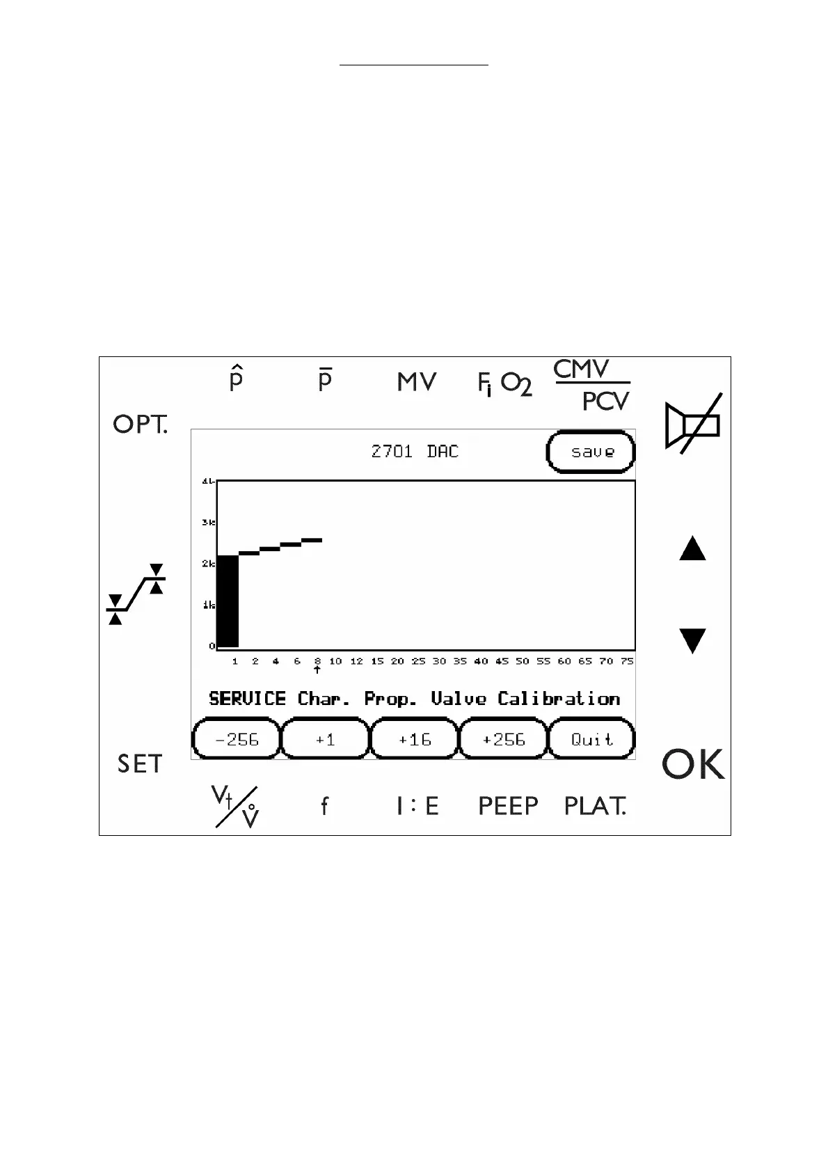
4.6.2.7 Characteristic of the Proportional Valve
Caution: The three procedures “Proportional Valve Calibration”, “Internal Flow Sensor
Calibration” and “Characteristic of the Proportional Valve” must always be
performed together in the order as in the manual, never individually.
1 Select CHARAC.PV to enter the Characteristic of the Proportional Valve screen.
2 Attach an external flow sensor to the drive gas outlet of the docking station.
3 To calibrate the proportional valve, select the increment keys (along the bottom edge of the
screen) until the flow meter displays the number that the on screen arrow is pointing to.
Fig. 43 Characteristic of the Proportional Valve screen
4 When each flow is achieved within the limits specified in the table below, select ENTER to step to
the next designated flow rate.
5 Set each flow (from 1 to 75 l/min) to the specified tolerance in the following table. Select ENTER
after each setting to step to the next designated flow rate (on screen arrow).
Caution: Pressing QUIT at any time during the procedure will cancel the session’s
settings and reload the previously stored calibration coefficients.