Preventive Maintenance
91
7 Reconnect the red plug of the test port on top of the pressure regulator for the driving gas. Adjust
the voltage of the internal flow sensor.
a Connect the measurement tips of a voltmeter to the X 5-1 and ground connector (module 2,
AVM 3-2)
b Select MAX to open the proportional valve.
c Turn the adjustment screw on top of the flow divider until you have a voltage of 4.6 ± 0.1 V at
the measuring points mentioned above
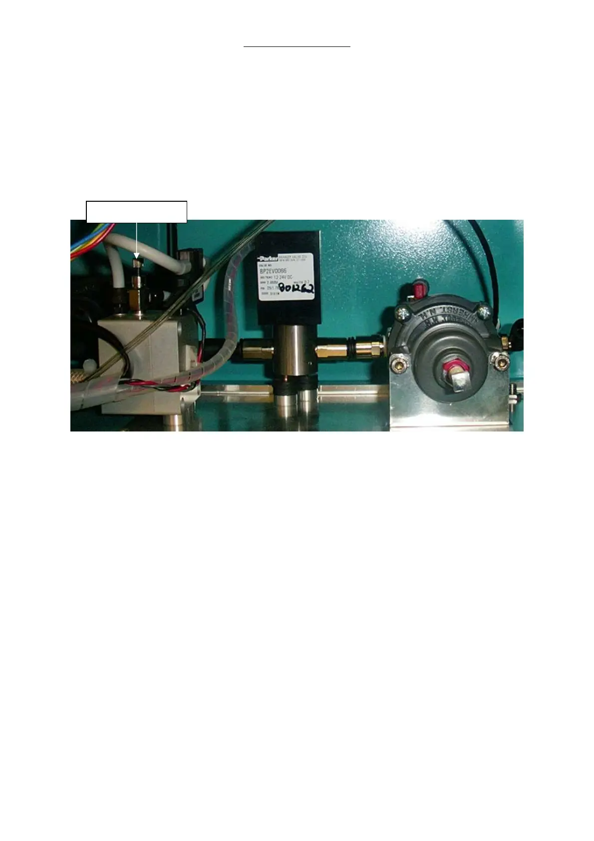
Fig. 41 Adjustment Screw on top of the Flow Divider
d Select MIN to close the proportional valve.
8 Save values in memory
a Select SAVE twice on the touch screen to store minimum and maximum values in memory.
b Select QUIT to return to the main menu.
Caution: Pressing QUIT at any time during the procedure will cancel the session’s
settings and reload the previously stored calibration coefficients.
Adjustment Screw