Repair Information
30
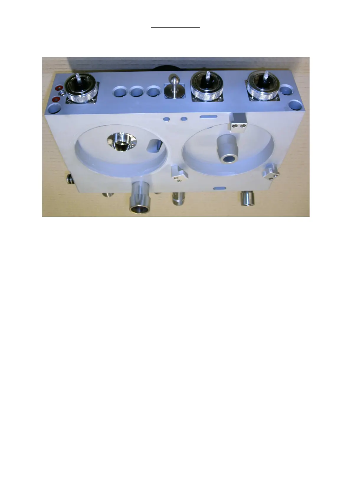
2.15.2 Bottom and back side view on the patient module
Fig. 8 Bottom and backside view on the patient module
Pos. Description
1
Fixing screws for locking bolt
2
Exhaust for driving gas
3
Driving gas in- and outlet to bellows dome
4
Thread for CO
2
absorber canister fixing, outlet from patient module to absorber
5
Inlet for re-breathing gas from absorber to patient module
6
Connector for bellows
7
Inlet for ambient air valve / emergency air valve
8
Port for anesthetic gas scavenging tube (30 mm cone)
6
7
8