Repair Information
38
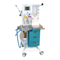
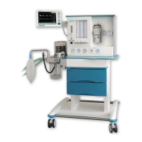
2.15.4 Components of the patient module
2.15.4.1 Ventilation bellows system
The ventilator’s driving system can be characterized as a constant flow generator. The driving gas of
this generator fills the bellows dome to compress the bellows. The breathing gas is pressed out of the
bellows into the circuit. Due to the weight of the descending bellows, it is self-filling when the driving
gas flow is stopped. The bellows control valve enables the escape of the driving gas.
2.15.4.2 Manual Respiration Bag / Reservoir
In the manual mode this device acts as a normal breathing bag, enabling the user to ventilate the
patient manually. In CMV mode this bag acts as a reservoir for fresh gas in the inspiration phase. In
the expiratory phase the re-breathing gas and the fresh gas are accumulated in this reservoir. The
bag’s in- and deflation corresponds to the volume balance of the breathing circuit and the patient.
When a volume loss occurs, the bag deflates breath by breath and finally collapses. Such a collapsing
breathing bag is an indicator for a leakage. The breathing bag must collapse if the fresh gas flow,
reduced by the patient’s uptake, is not able to compensate the leakage.
2.15.4.3 CO
2
absorber
The soda lime inside the absorber retains the carbon dioxide from the re-breathing gas. The flow
orientation is upstream.
2.15.4.4 Inspiratory and expiratory valves
To ensure the gas flow direction the two one-way-valves in the inspiratory limb and expiratory limb are
integrated inside the patient module. These valves are seen activating form the top of the module.
2.15.4.5 Airway pressure relief valve
In CMV position the APL valve closes the re-breathing system towards the scavenging line and limits
the reservoir pressure to a constant value of 2 cmH
2
O. In manual mode the APL valve acts as a
normal spring loaded pressure relief valve, limiting the maximum pressure in the re-breathing system.
2.15.4.6 Room Air valve
Due to the tendency of the descending bellows to refill itself by creating a negative pressure inside the
bellows this valve prevents the patient from becoming any negative pressure by opening the
diaphragm and allowing ambient air to refill the bellows.
2.15.4.7 Diaphragm/Membrane valves
Inside the patient module valves operate the expiratory line, the bellows dome outlet and the fresh gas
decoupling line during the CMV-mode. These valves are controlled by pressured gas to open or close
the valve’s path. All valves are open when not inflated. The power gas for these valves is controlled by
the ventilator’s valve bank using a supply pressure of about 20 kPa (200 mbar; 2.9 PSI)// 25 kPa (250
mbar; 3,63PSI) from the ventilator pneumatic.