Preventive Maintenance
75
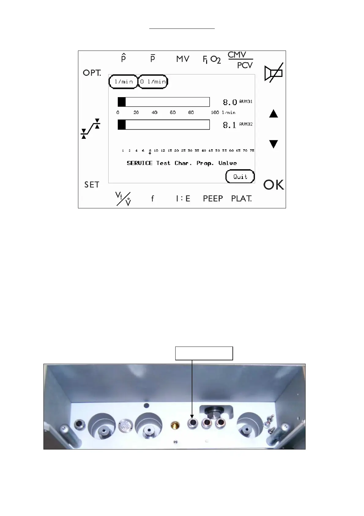
Fig. 29 Proportional valve test screen
n Attach a flow meter to measure flow directly from the Drive Gas Outlet.
WARNING Never block airflow at the drive gas outlet. Blocking the airflow at the drive gas
outlet raises internal pressure above specified limits and will result in
permanent damage to internal sensors.
o Use the UP/DOWN arrow keys to move the arrow to the desired flow.
p Select ENTER to start the flow of gas.
q Verify the AVM 3-1 and AVM 3-2 values match the flow rate settings and the flow meter
measurement (± 10%) after stabilization.
r Select 0 l/min to stop the flow of gas.
s Select QUIT to return to the test menu.
Fig. 30 Drive Gas Outlet
t Reinstall the Patient Module.
Drive Gas Outlet