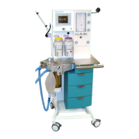
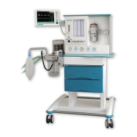
Theory of Operation
0 Table of Contents
0
Table of Contents ............................................................................................................................. 3
0.1
Table of Figures ........................................................................................................................ 6
1
General Information.......................................................................................................................... 7
1.1
Guidelines ................................................................................................................................. 7
1.2
Product improvements .............................................................................................................. 7
1.3
Manufacturer’s Liability ............................................................................................................. 7
1.4
Manufacturer’s specification ..................................................................................................... 8
1.5
Updating status ......................................................................................................................... 8
1.6
Warning, Precautions and Notes .............................................................................................. 9
1.6.1
Warnings............................................................................................................................ 9
1.6.2
Precautions...................................................................................................................... 10
1.6.3
Notes................................................................................................................................ 11
2
Theory of Operation ....................................................................................................................... 13
2.1
Microprocessor-Controlled Ventilator...................................................................................... 13
2.2
Patient Module ........................................................................................................................ 13
2.3
Gas Conditioning Unit ............................................................................................................. 13
2.4
The Ventilator Unit .................................................................................................................. 13
2.5
Adjustable Alarms ................................................................................................................... 13
2.5.1
P
max
limiting on alarm violation......................................................................................... 14
2.6
Fresh Gas Decoupling ............................................................................................................ 14
2.7
Compliance compensation...................................................................................................... 14
2.8
Electrical supply ...................................................................................................................... 15
2.8.1
Electrical components...................................................................................................... 16
2.9
Power supply module.............................................................................................................. 17
2.9.1
Connectors on power supply board AVM 2-1.................................................................. 18
2.9.2
Fuses on power supply board AVM 2-1........................................................................... 19
2.9.3
Charging / discharging control for the battery:................................................................. 20
2.9.4
Status Indicators Of Battery Control: ............................................................................... 20
2.10
Module 1.............................................................................................................................. 21
2.10.1
Connectors on module 1.............................................................................................. 22
2.11
Ventilator Module 2, AVM 3-1 and AVM 3-2 ....................................................................... 23
2.11.1
Parts list module 2........................................................................................................ 24
2.11.2
Connectors on module 2.............................................................................................. 24
2.11.2.1
Plug connectors on board AVM 3-1 ........................................................................ 24
2.11.2.2
Plug connectors on board AVM3-2 ......................................................................... 25
2.12
Display................................................................................................................................. 25
2.13
Battery ................................................................................................................................. 25
2.14
Ventilator pneumatic............................................................................................................ 26
2.14.1
Ventilator pneumatic drive............................................................................................ 27
2.14.2
HP pressure reducer .................................................................................................... 27
2.14.3
LP- double stage pressure reducer.............................................................................. 27
2.14.4
Solenoid valves MV1 to MV4 ....................................................................................... 27
2.14.5
Pneumatic driving module............................................................................................ 28
2.14.6
Flow metering module.................................................................................................. 28
2.14.7
Tube color coding......................................................................................................... 28
2.15
The patient module (circle system) ..................................................................................... 29
2.15.1
Front and back side view on the patient module.......................................................... 29
2.15.2
Bottom and back side view on the patient module....................................................... 30
2.15.3
Functional representations of the patient module........................................................ 31
2.15.3.1
CMV mode, inspiration............................................................................................ 32
2.15.3.2
CMV mode, expiration............................................................................................. 33
2.15.3.3
Manual mode, inspiration ........................................................................................ 34
2.15.3.4
Manual mode, expiration......................................................................................... 35
2.15.3.5
Spontaneous mode, inspiration............................................................................... 36
2.15.3.6
Spontaneous mode, expiration................................................................................ 37
2.15.4
Components of the patient module.............................................................................. 38
2.15.4.1
Ventilation bellows system ...................................................................................... 38
2.15.4.2
Manual Respiration Bag / Reservoir........................................................................ 38
2.15.4.3
CO
2
absorber........................................................................................................... 38