3.3 Input Channel Settings
61
3
3
Chapter 3 Settings
Make these channel settings for pulse and logic measurements.
(See "Integration (Count) Measurement Settings" (p .62) and "Revolution Measurement
Settings" (p .63) for pulse measurements.)
Make these settings on the [CH] screen.
See: "Key Setting Procedure" (p .53)
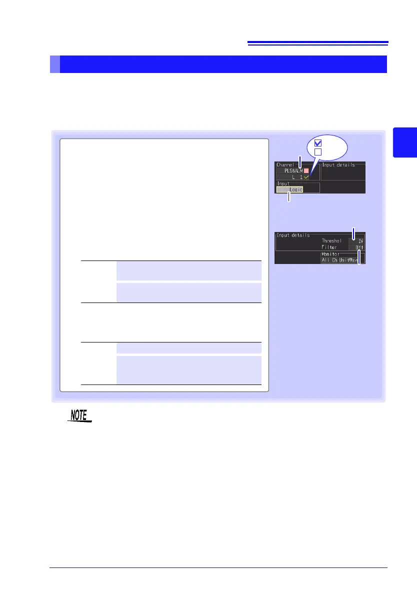
Pulse or Logic Measurement Settings
1 Select the input unit (PLS&ALM) and channel
(P1 to P8), and check the box to enable the
channel.
2 Select [Logic].
When Logic is selected, the channel display automatically
changes from P1 to L1.
3 Select the High/Low reference (threshold) val-
ues.
4 Select a filter setting.
Setting options:( : default setting)
1V
Judge 1.0 V or higher as HIGH, and 0 to
0.5 V as LOW.
4V Judge 4.0 V or higher as HIGH, and 0 to
1.5 V as LOW.
Setting options:( : default setting)
Off
Filter is disabled.
On Filter is enabled. Prevents incorrect
counts due to relay contact chatter
(noise).
1
2
: On
: Off
3
4
Channels L1 to L8 share the same On/Off state. For example, when L1
and L2 are both enabled, disabling L1 also disables L2. Threshold and fil
-
ter settings are specific to each channel.