7.2 Displaying Trends
96
Displayed waveform and measured value
Notation meaning
Symbol Measurement Items Symbol Measurement Items Symbol Measurement Items
Freq
Frequency Irms RMS current
Uunb0
Uunb
Voltage zero-phase
unbalance factor
current
Negative-phase
unbalance factor
f10s
Frequency 10 sec
(Freq10s)
IrmsAVG
Average RMS current
(when avg is selected)
Iunb0
Iunb
Current zero-phase
unbalance factor
current
Negative-phase
unbalance factor
Upk+
Upk-
Voltage waveform
peak+
Voltage waveform
peak-
Idc
Current DC UharmH
High-order
harmonic voltage com-
ponent
Ipk+
Ipk-
Current waveform
peak+
Current waveform
peak-
P
Active power IharmH
High-order
harmonic current com-
ponent
Urms
RMS voltage
(phase/line)
S
Apparent power
Uthd-F
Uthd-R
Total harmonic voltage
distortion factor
UrmsAVG
Average RMS voltage
(when avg is selected)
Q
Reactive power
Ithd-F
Ithd-R
Total harmonic current
distortion factor
Udc
Voltage DC PF Power factor KF K factor
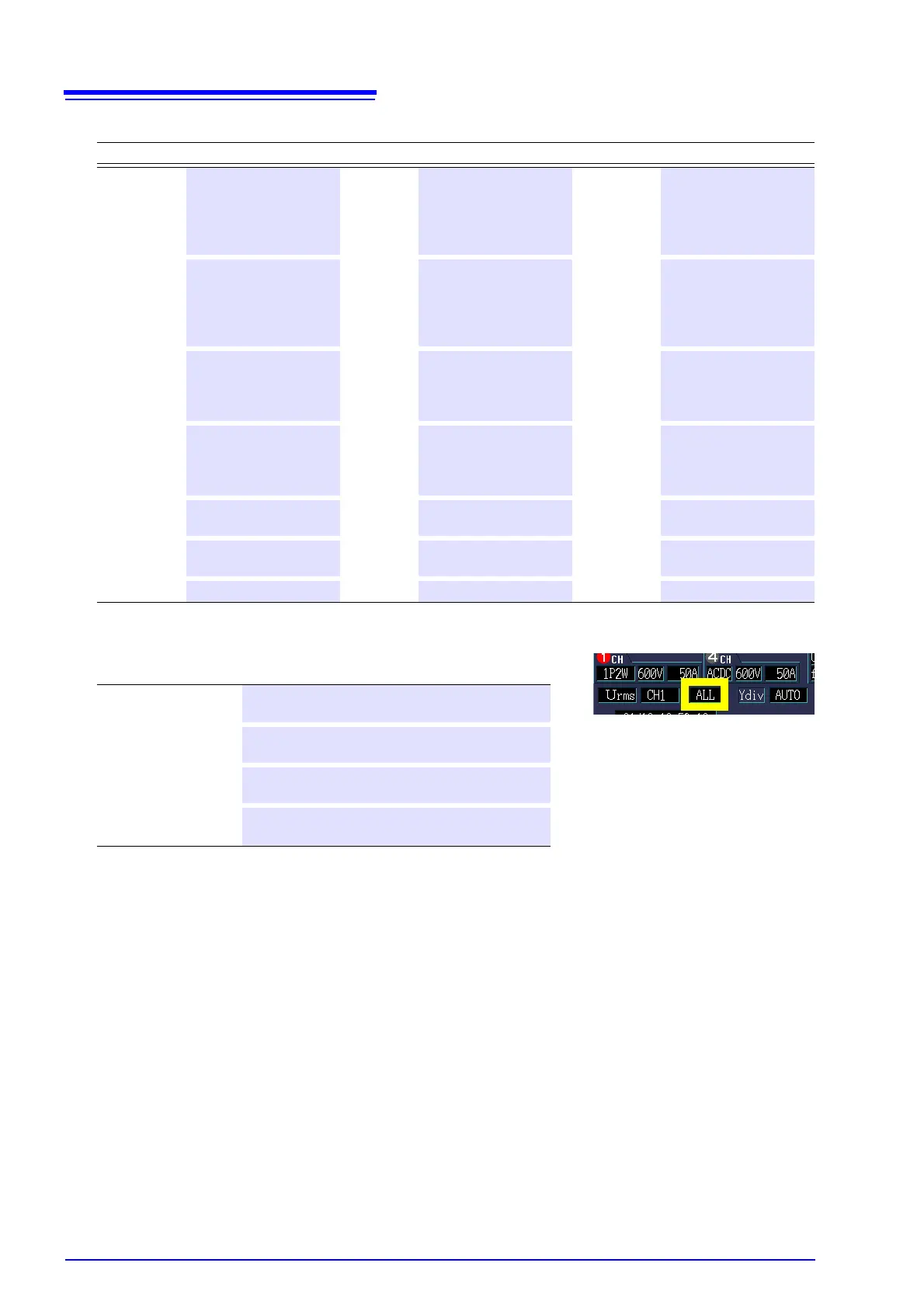
Settings:( : Default)
MAX
Displays the maximum value during the TIME-
PLOT interval.
MIN
Displays the minimum value during the TIME-
PLOT interval.
AVG
Displays the average value during the TIME-
PLOT interval.
ALL
Displays the maximum, minimum, and average
values during the TIMEPLOT interval.

 Loading...


