13.10 Calculation Formula
200
Note) c: measured channel, M: number of samples per period, s: number of sampling points
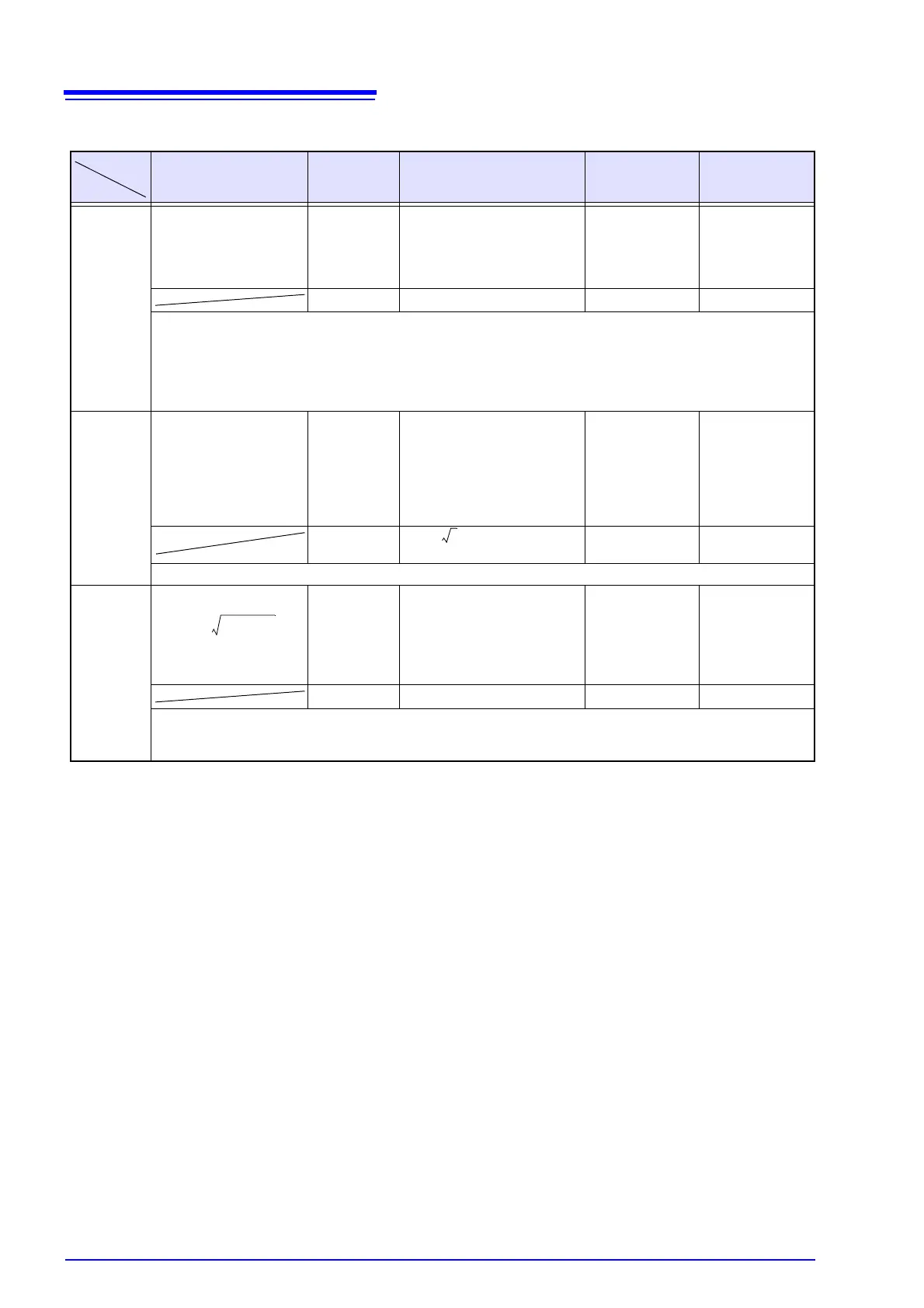
Active Power (P), Apparent Power (S), Reactive Power (Q)
Single Phase 2-wire
1P2W
Single Phase
3-wire
1P3W
3-Phase, 3-Wire,
2-Measurement
3P3W2M
3-Phase, 3-Wire,
3-Measurement
3P3W3M
3-Phase, 4-Wire
3P4W
P P
1
Pc=
P
1
P
2
P
1
P
2
P
1
P
2
P
3
P
1
P
2
P
3
Psum=P
1
+P
2
Psum=P
1
+P
2
Psum=P
1
+P
2
+P
3
Psum=P
1
+P
2
+P
3
• Calculated with 10 waveforms (50 Hz measurement) or 12 waveforms (60 Hz measurement). For 400 Hz measure-
ment, the calculation is performed with 80 waveforms.
• For 3P3W3M and 3P4W systems, phase voltage is used for waveform voltage Ucs.
(3P3W3M: U1s=(U1s-U3s)/3, U2s=(U2s-U1s)/3, U3s=(U3s-U2s)/3)
• The polarity sign for active power indicates power flow direction: positive (+P) for forward power (consumption), and
negative (-P) for reverse power (regeneration), and indicates net current flow for power.
S S
1
Sc= Uc×Ic
(When P>, make P =S.)
S
1
S
2
S
1
S
2
S
1
S
2
S
3
S
1
S
2
S
3
Ssum=S
1
+S
2
Ssum= Ssum=S
1
+S
2
+S
3
Ssum=S
1
+S
2
+S
3
For 3P3W3M and 3P4W systems, phase voltage is used for waveform voltage Uc.
Q Q
1
Qc=
Q
1
Q
2
Q
1
Q
2
Q
1
Q
2
Q
3
Q
1
Q
2
Q
3
Qsum=Q
1
+Q
2
Qsum=Q
1
+Q
2
Qsum=Q
1
+Q
2
+Q
3
Qsum=Q
1
+Q
2
+Q
3
• The polarity sign (sic) for reactive power (Q) is indicated by [none] for lag or [-] for lead.
• The reverse of the fundamental wave reactive power (using k = 1 (1st order)) after calculating the harmonic reactive power
for each measurement channel (c) is used as the polarity sign sic. (See the harmonic reactive power formula.)
1
M
-- -
Ucs Ics
S 0=
M 1–

 Loading...


