1 Confirm that the instrument
and printer are turned off.
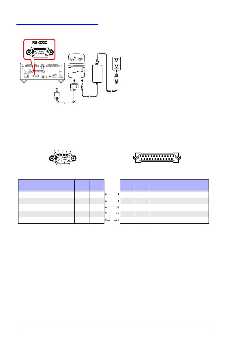
2 Connect the RS-232C Cable
to the RS-232C connectors
on the instrument and
printer.
3 Turn the instrument and
printer on.
Printer (Example)
AC Adapter
RS-232C Cable
25 ....................... 14
Printer (25-pin) Connector (Example)RM3545 (9-pin) Connector
Pin
Signal
Name
Circuit name
2 TxD Transmit Data
3 RxD Receive Data
7 GND Signal or Common Ground
4 RTS Request to Send
5 CTS Clear to Send
Circuit name
Signal
Name
Pin
Receive Data RxD 2
Transmit Data TxD 3
Signal or Common Ground GND 5
6 7 8 9
1 2 3 4 5
Connector Pinouts
13 ....................... 1
Be sure to check the connector pin assign-
ments for the printer being used.
2