Appendix 13 Making Your Own Measurement Leads, Making Connections to the Multiplexer
A30
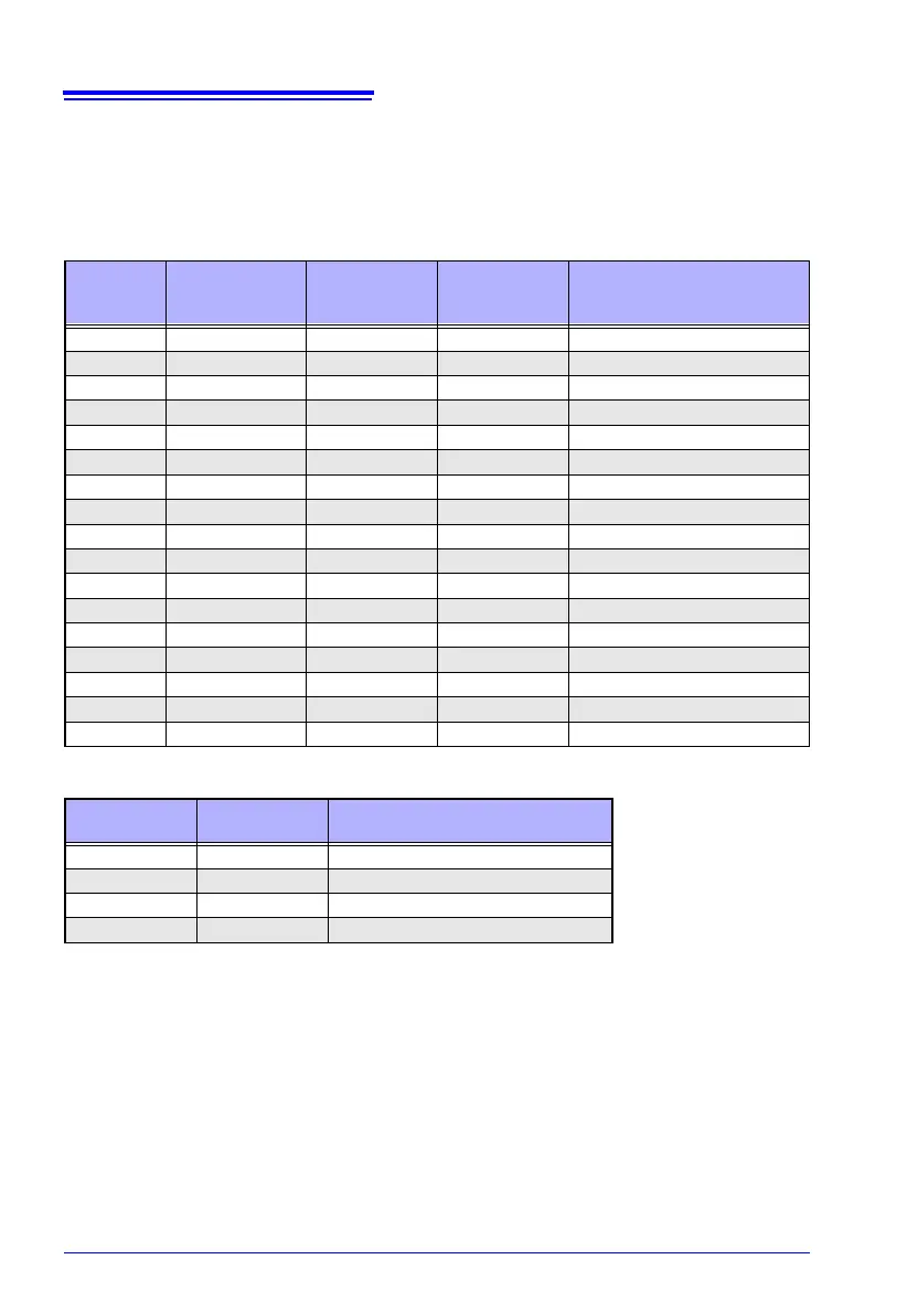
• Refer to the block diagram (p. A1) for internal circuit details.
• Wiring resistance in excess of the values listed in the table below may cause a current
fault, making measurement impossible. When using measurement current 1 A ranges,
keep the wiring resistance (cable line resistance, relay on-resistance) as well as the con-
tact resistance between the measurement targets and probe low.
LP OFF
LP ON
* When using the Z3003 Multiplexer Unit, the unit’s internal wiring resistance (including
relays) is included. The self-test function can be used to verify that the unit’s internal wir-
ing resistance is 1 or below.
See: "8.6 Performing the Multiplexer Unit Self-test" (p.166)
Range
100 M range
high-precision
mode
Current
switching
Measurement
Current
SOURCE B - SOURCE A
(Other than measurement
target) *
10 m
−−1 A 1.5
100 m − High 1 A 1.5
100 m
− Low 100 mA 15
1000 m − High 100 mA 15
1000 m
− Low 10 mA 150
10 − High 10 mA 150
10
− Low 1 mA 1 k
100 − High 10 mA 100
100
− Low 1 mA 1 k
1000 − − 1 mA 1 k
10 k
−−1 mA 1 k
100 k − − 100 A 1 k
1000 k
−−10 A1 k
10 M − − 1 A 1 k
100 M ON
− 100 nA 1 k
100 M OFF − 1 A or less 1 k
1000 M OFF
− 1 A or less 1 k
Range
Measurement
Current
SOURCE B - SOURCE A
(Other than measurement target) *
1000 m 1 mA 2
10 500 A 5
100 50 A50
1000 5 A 500