D2 Drive User Guide v1.8 4. Wiring
HIWIN Mikrosystem Corp. 42
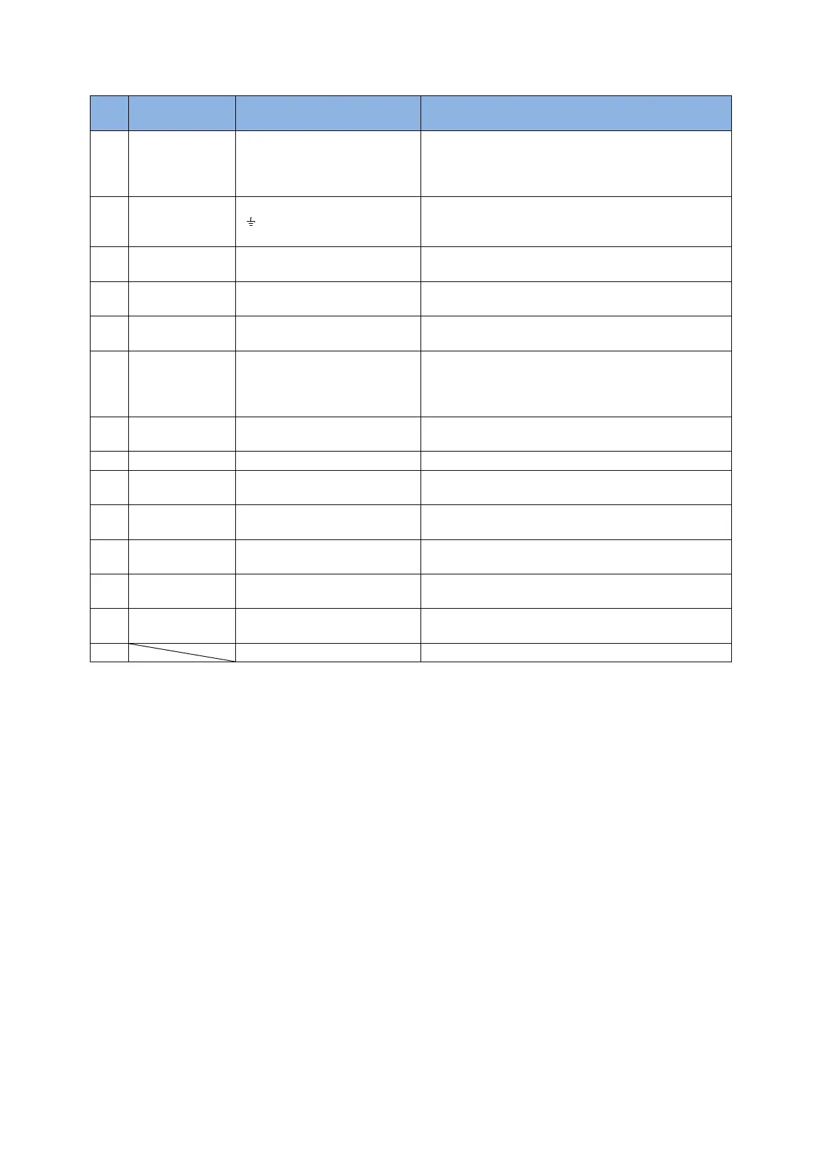
Table 4-1
L1, L2: Single-phase 200-240 Vac, 50/60Hz
L1, L2, L3: Three-phase 200-240 Vac, 50/60Hz
(The frame D model is only allowed connecting to
three-phase AC power)
Frame A-C: CN1
( , U, V, W)
Frame D: CN2 (U, V, W)
Connected to motor, three-phase motor power
Frame A-C: CN1 (R-, R+)
Frame D: CN1 (B1, B2, B3)
Connected to regenerative resistor
(optional/installed according to actual application)
Frame A-D: CN1
(L1C, L2C)
Drive control and I/O power
(L1C, L2C: Single-phase 200-240 Vac, 50/60Hz)
Frame A-C: CN2 (B-, B+)
Frame D: CN6 (O5-, O5+)
Connected to brake
(optional/installed according to actual application)
Connected to PC (for parameter setting; to be
removed after setting)
Using mini USB to connect with PC for monitoring
drive, doing test runs, or writing parameters, etc.
Frame A-C: CN4, CN5
Frame D: CN4
Connected to host controller by using Modbus
communication protocol
Connected to host controller
Connected to motor encoder
Connected to host controller by using EtherCAT
communication protocol
Connected to safety device
Connected to DC reactor
(optional/installed according to actual application)