D2 Drive User Guide v1.8 4. Wiring
HIWIN Mikrosystem Corp. 77
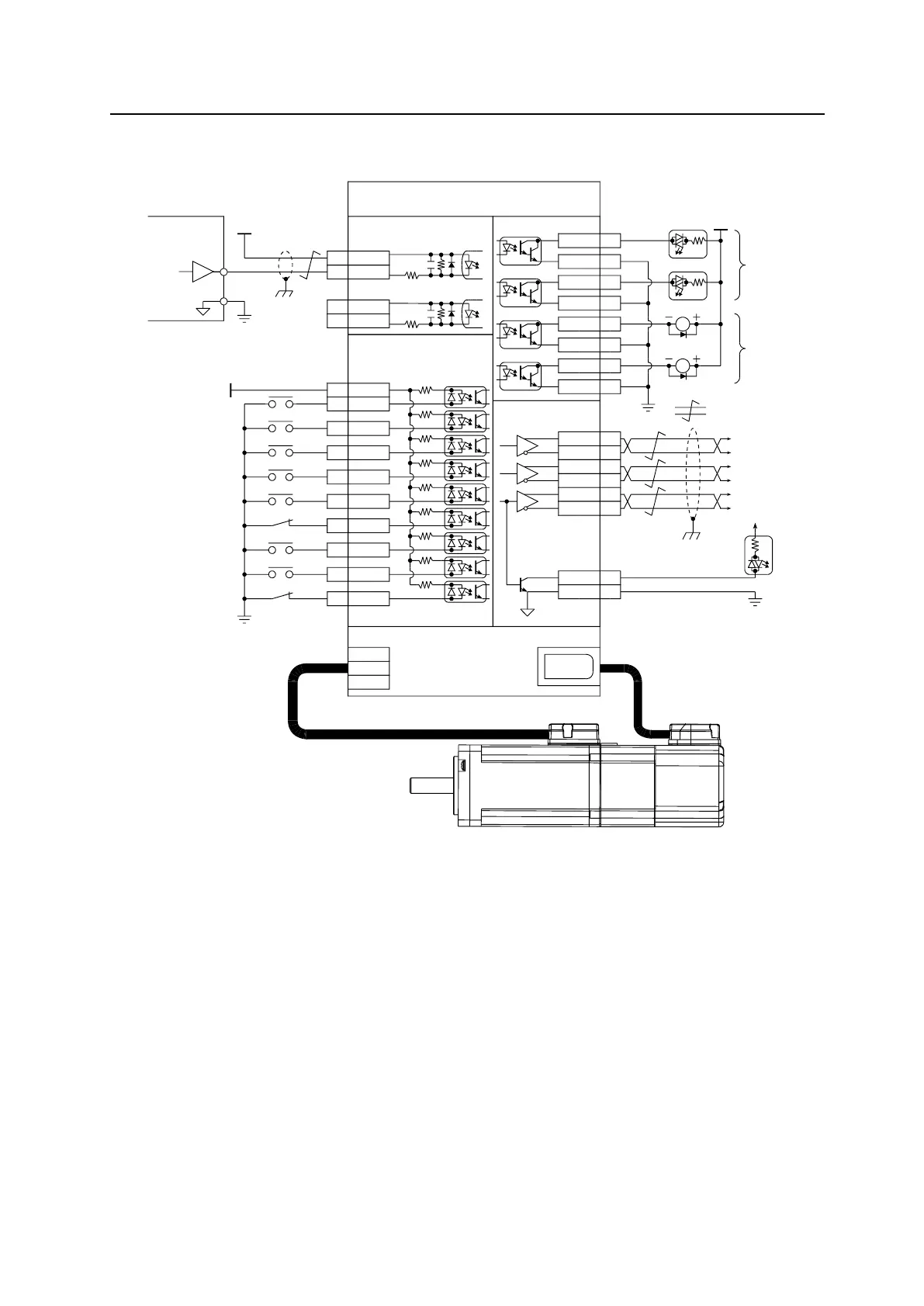
4.6.3.3. 5V TTL interface with PWM 50%
Wiring example for the host controller having the 5V TTL interface with PWM 50%:
Fig. 4-44
APPD
CHK
DRN
DWG NONAME SHEET
HIWIN CONFIDENTIAL
,
DATE
HIWIN® MIKROSYSTEM CORP.
W
V
U
CN1 CN7
CN6
4 CWL-
220
2K
220
2K
6 CCWL-
COM7
I133
I230
I329
I427
I528
I626
I732
I831
I99
4.7K
CN6
21A
22/A
48B
49/B
23Z
24/Z
19CZ
CN6
Encoder output
25SG
Signal output
Signal input
Velocity / Torque mode
ZSP
SVN
GNS
29
LL
MOD
CE
RL
24V
0V
0V
5VDC
General input
Definited by user
A-phase
output
Z output (open collector)
0V
Controller
B-phase
output
Z-phase
output
PWM 50% command
mega-fabs
D2 Series Drive
3 CWL+
5 CCWL+
D2-ENE15B
5V TTL type
05/16/2014
B 1-1D2-ENE15
Erick Wang
0V
General output
Definited by user
PWM
D2 wiring example:
PWM 100% command for velocity / torque mode
control. Controller output type is 5V TTL.
( :Twisted pair)
Ic=0.6A(Max.)
Vce=40V(Max.)
CN6
O1+ 35
O1- 34
O2+ 37
O2- 36
O3+ 39
O3- 38
O4+ 11
O4- 10
24V
R
RDY
ALM
INP
Photo-
Coupler
wiring
Relay
wiring
R
Ver.B: 5V TTL wiring error. 5VDC should put into CN6/pin3.
General-purpose
input; its function
can be assigned
by the user.
General-purpose output;
its function can be
assigned by the user.