About the Anybus Communicator for PROFINET 11
Doc: HMSI-27-309, Rev. 3.11Anybus Communicator PROFINET User Manual
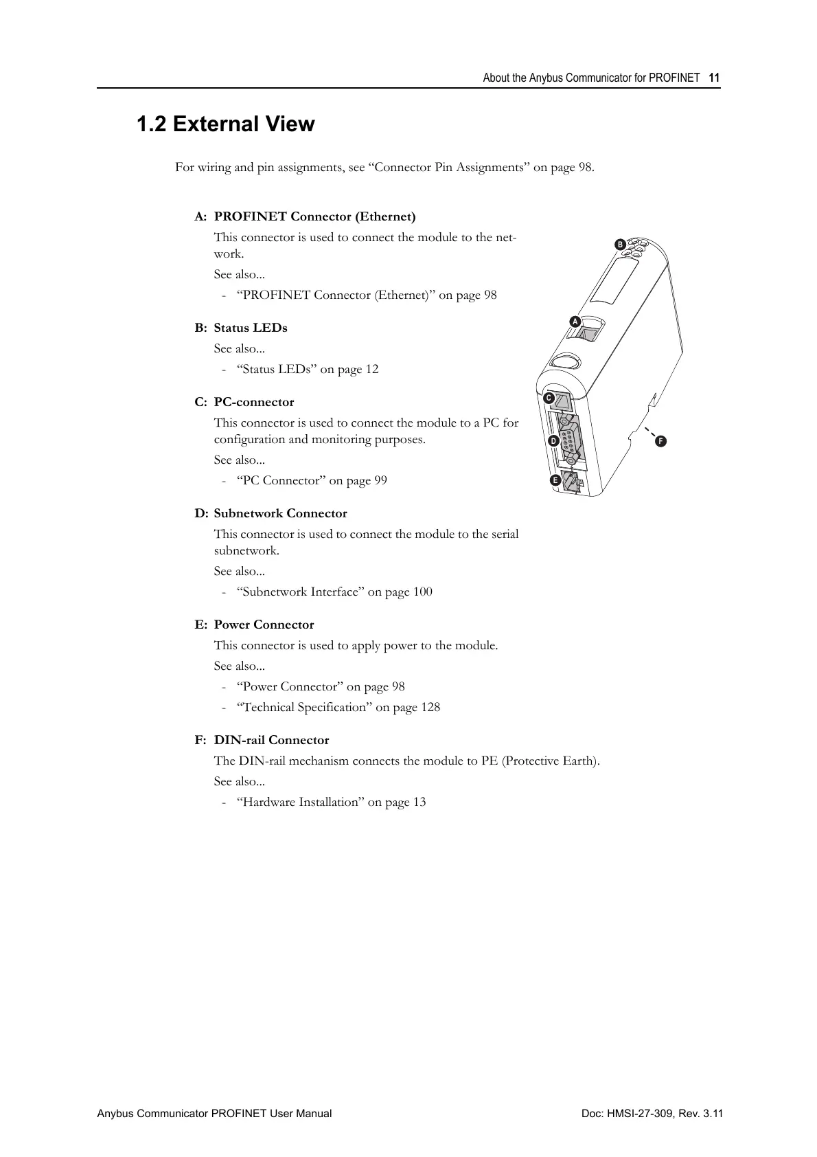
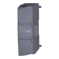
1.2 External View
For wiring and pin assignments, see “Connector Pin Assignments” on page 98.
A: PROFINET Connector (Ethernet)
This connector is used to connect the module to the net-
work.
See also...
- “PROFINET Connector (Ethernet)” on page 98
B: Status LEDs
See also...
- “Status LEDs” on page 12
C: PC-connector
This connector is used to connect the module to a PC for
configuration and monitoring purposes.
See also...
- “PC Connector” on page 99
D: Subnetwork Connector
This connector is used to connect the module to the serial
subnetwork.
See also...
- “Subnetwork Interface” on page 100
E: Power Connector
This connector is used to apply power to the module.
See also...
- “Power Connector” on page 98
- “Technical Specification” on page 128
F: DIN-rail Connector
The DIN-rail mechanism connects the module to PE (Protective Earth).
See also...
- “Hardware Installation” on page 13