Basic Operation 22
Doc: HMSI-27-309, Rev. 3.11Anybus Communicator PROFINET User Manual
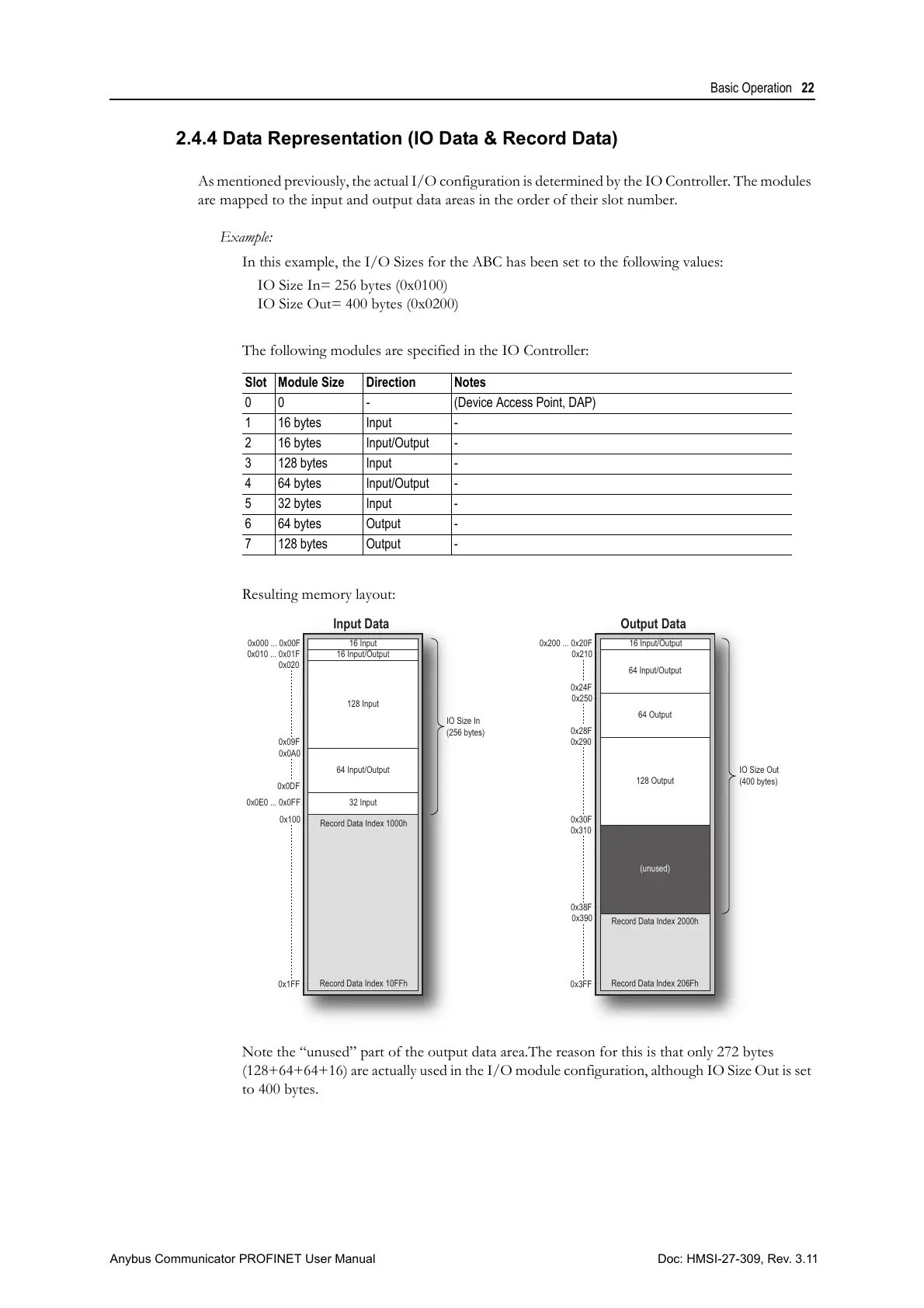
2.4.4 Data Representation (IO Data & Record Data)
As mentioned previously, the actual I/O configuration is determined by the IO Controller. The modules
are mapped to the input and output data areas in the order of their slot number.
Example:
In this example, the I/O Sizes for the ABC has been set to the following values:
IO Size In= 256 bytes (0x0100)
IO Size Out= 400 bytes (0x0200)
The following modules are specified in the IO Controller:
Resulting memory layout:
Note the “unused” part of the output data area.The reason for this is that only 272 bytes
(128+64+64+16) are actually used in the I/O module configuration, although IO Size Out is set
to 400 bytes.
Slot Module Size Direction Notes
0 0 - (Device Access Point, DAP)
1 16 bytes Input -
2 16 bytes Input/Output -
3 128 bytes Input -
4 64 bytes Input/Output -
5 32 bytes Input -
6 64 bytes Output -
7 128 bytes Output -
Input Data Output Data
16 Input0x000 ... 0x00F
0x0A0
16 Input/Output0x010 ... 0x01F
0x09F
0x0DF
0x1FF
0x020
16 Input/Output0x200 ... 0x20F
128 Input
128 Output
(unused)
32 Input0x0E0 ... 0x0FF
64 Input/Output
64 Output
64 Input/Output
Record Data Index 1000h
Record Data Index 10FFh
Record Data Index 2000h
Record Data Index 206Fh
IO Size In
(256 bytes)
IO Size Out
(400 bytes)
0x30F
0x3FF
0x290
0x38F
0x310
0x210
0x24F
0x100
0x250
0x28F
0x390