Basic Operation 16
Doc: HMSI-27-309, Rev. 3.11Anybus Communicator PROFINET User Manual
2.2 Data Exchange Model
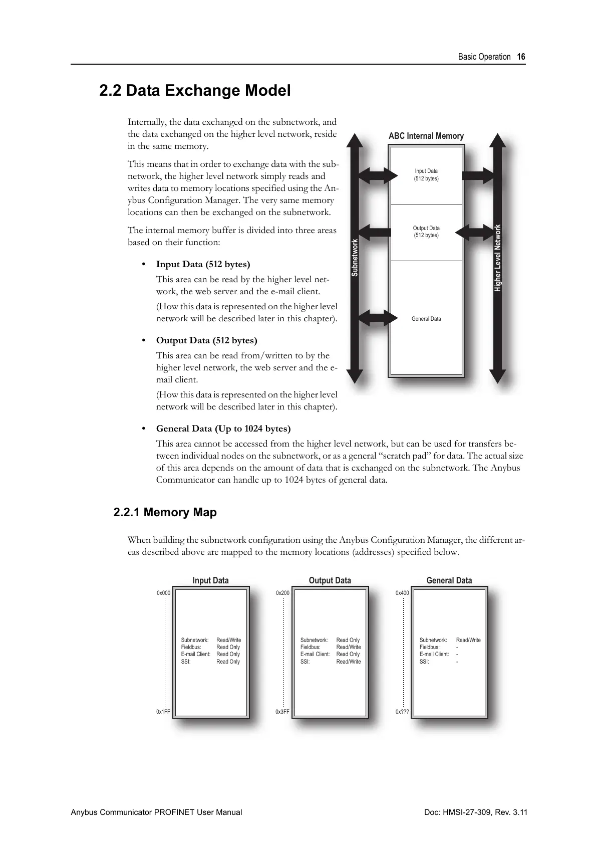
Internally, the data exchanged on the subnetwork, and
the data exchanged on the higher level network, reside
in the same memory.
This means that in order to exchange data with the sub-
network, the higher level network simply reads and
writes data to memory locations specified using the An-
ybus Configuration Manager. The very same memory
locations can then be exchanged on the subnetwork.
The internal memory buffer is divided into three areas
based on their function:
• Input Data (512 bytes)
This area can be read by the higher level net-
work, the web server and the e-mail client.
(How this data is represented on the higher level
network will be described later in this chapter).
• Output Data (512 bytes)
This area can be read from/written to by the
higher level network, the web server and the e-
mail client.
(How this data is represented on the higher level
network will be described later in this chapter).
• General Data (Up to 1024 bytes)
This area cannot be accessed from the higher level network, but can be used for transfers be-
tween individual nodes on the subnetwork, or as a general “scratch pad” for data. The actual size
of this area depends on the amount of data that is exchanged on the subnetwork. The Anybus
Communicator can handle up to 1024 bytes of general data.
2.2.1 Memory Map
When building the subnetwork configuration using the Anybus Configuration Manager, the different ar-
eas described above are mapped to the memory locations (addresses) specified below.
General Data
ABC Internal Memory
Input Data
(512 bytes)
Subnetwork
Output Data
(512 bytes)
Higher Level Network
Input Data Output Data General Data
Subnetwork:
Fieldbus:
E-mail Client:
SSI:
Subnetwork:
Fieldbus:
E-mail Client:
SSI:
Subnetwork:
Fieldbus:
E-mail Client:
SSI:
Read/Write
Read Only
Read Only
Read Only
Read Only
Read/Write
Read Only
Read/Write
Read/Write
-
-
-
0x000 0x200
0x1FF 0x3FF
0x400
0x???