5-28
BF135A•BF150A
• ECM Troubleshooting
DTC 0-2, 0-5, 0-8: Inside of ECM is faulty
1. Symptom reproduction test
-1. Connect the HDS pocket tester.
-2. Turn the ignition switch ON and wait for 1 second or
more.
-3. Clear the DTC once.
-4. Start the engine and check the DTC again.
Does the DTC 0-2, 0-5, and/or 0-8 appear?
YES – Substitute a known-good ECM and recheck.
NO – Temporary failure inside ECM (Disappeared)
• MAP Sensor Troubleshooting
DTC 3-1: MAP sensor voltage is low
1. Symptom reproduction test
-1. Connect the HDS pocket tester and clear the DTC
once. If the DTC can not be cleared, go on the trou-
bleshooting.
-2. Turn the ignition switch ON.
-3. Check the MAP sensor voltage using the HDS pocket
tester.
Is the measured voltage 0.22 to 3.15V?
YES – Temporary failure (Disappeared)
NO – Perform “2. MAP sensor signal line short-cir-
cuit test”.
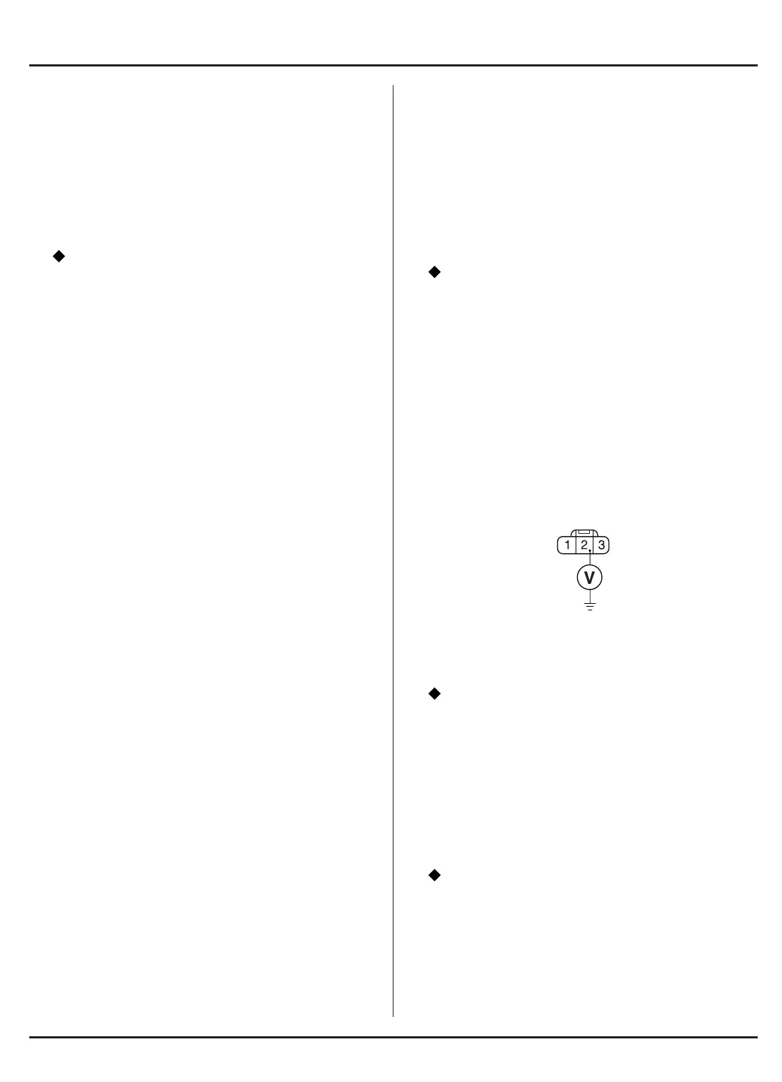
2. MAP sensor signal line short-circuit test
-1. Turn the ignition switch OFF and disconnect the MAP
sensor 3P connector.
-2. Disconnect the ECM connector A.
-3. Check for the continuity between the No. 2 (White/Red)
terminal of the MAP sensor harness side 3P connec-
tor and the body ground.
Is there the continuity?
YES – Repair short in the wire between the MAP
sensor and ECM.
NO – Perform “3. MAP sensor check”.
3. MAP sensor check
-1. Connect the ECM connector A and the MAP sensor
3P connector.
-2. Turn the ignition switch ON and read the MAP sensor
voltage using the HDS pocket tester.
Is the voltage 2.76 – 2.96V?
YES – Substitute a known-good ECM and recheck.
NO – Replace the MAP sensor.
MAP SENSOR HARNESS
SIDE 3P CONNECTOR
PB (WHITE/RED)
VIEWED FROM THE
TERMINAL SIDE












 To Next Page