BF135A•BF150A
5-90
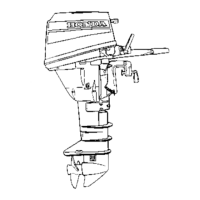
5. ECT sensor 4 check
-1. Turn the ignition switch OFF and disconnect the ECT
sensor 4 2P connector.
-2. Measure the voltage between the No.1 and No.2 ter-
minals of the ECT sensor 4 side 2P connector.
Is there the resistance corresponding to the engine
coolant temperature?
YES – Substitute a known-good ECM and recheck.
NO – Replace the ECT sensor 4.
• A/F Sensor Heater Troubleshooting
MIL blinks 41 times
1. Symptom reproduction test
-1. Reset the ECM.
-2. Start the engine and run it at 3,000 rpm for 5 minutes
or more to warm up.
-3. Check the MIL.
Does the MIL come ON?
YES – Perform "2. A/F relay check".
NO – Temporary failure (Disappeared)
2. A/F relay check
-1. Turn the ignition switch OFF and connect the test har-
ness.
Hold the sensor connector connected.
-2. Disconnect the A/F sensor 4P connector.
-3. Turn the ignition switch ON. Measure the voltage
between the test harness C-4 terminal and the engine
ground.
Is there the battery voltage?
YES – Perform "4. A/F heater check".
NO – Check the A/F relay and replace if necessary.
If it is normal, go to the step 4.
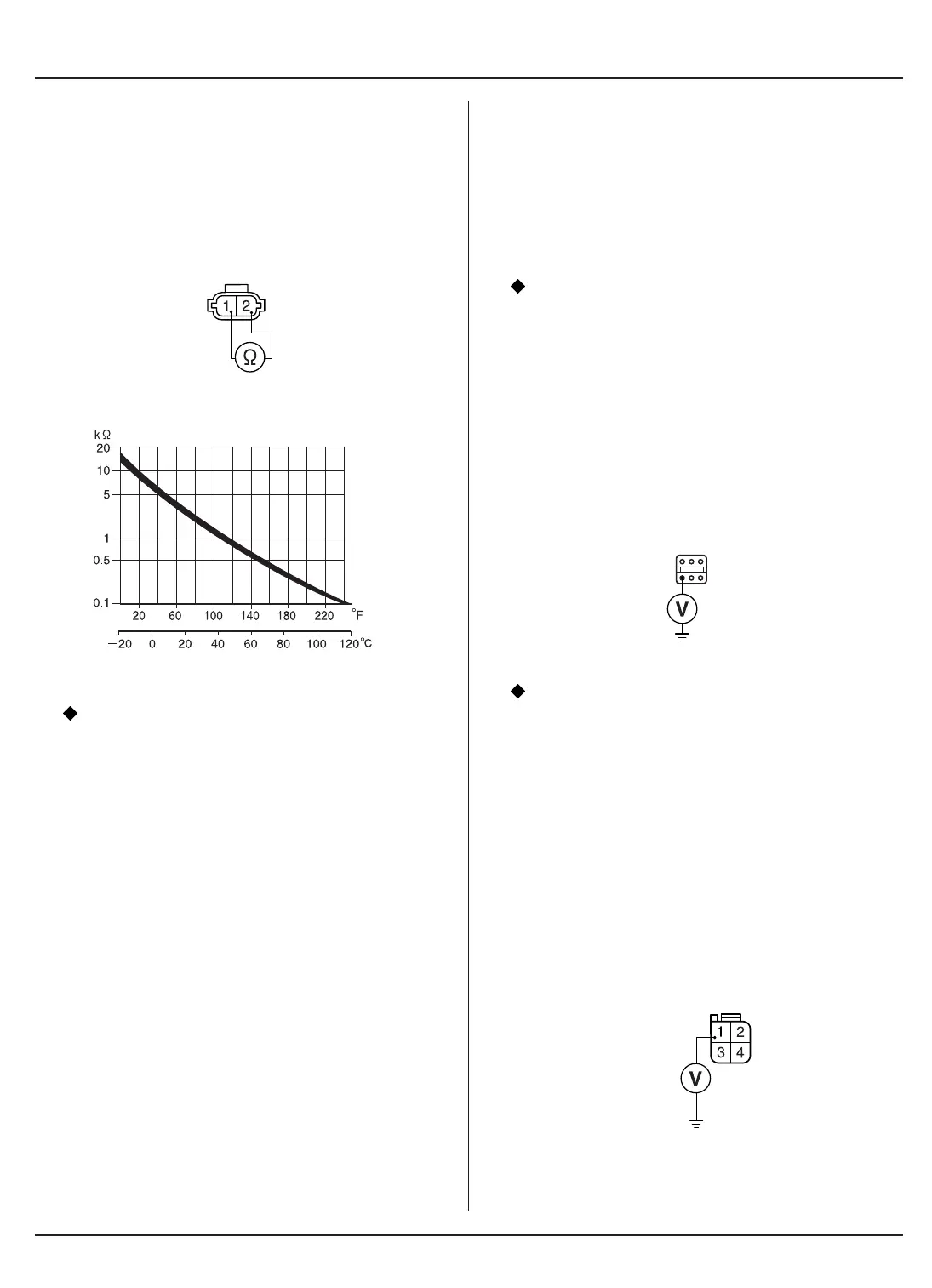
-4. Turn the ignition switch OFF and disconnect the A/F
relay 4P connector.
-5. Measure the voltage between the No.1 (White/ Green)
terminal of the A/F relay harness side 4P connector
and the engine ground.
• Note that the battery voltage is constantly applied to
the White/Green terminal. Take care not to short-cir-
cuit the terminal.
A/F RELAY HARNESS SIDE
4P CONNECTOR
VIEWED FROM THE TERMINAL SIDE
C-4
RESISTANCE
ECT SENSOR 4 SIDE
2P CONNECTOR
VIEWED FROM THE TERMINAL SIDE
ENGINE COOLANT TEMPERATURE
+B
(WHITE/GREEN)
 Loading...