2-45
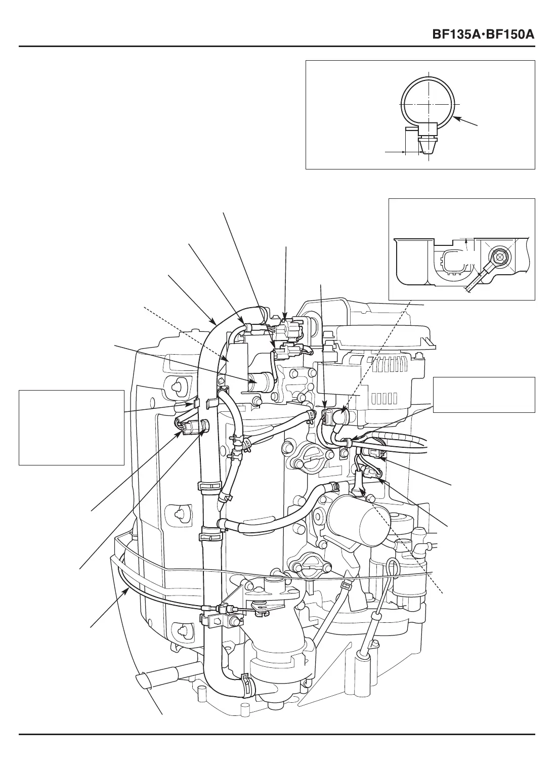
10. CABLE/HARNESS ROUTING
After securing the cables and harnesses with the harness band
clips, cut the end of the harness band clips so that the projected
length is 5 – 10 mm (0.2 – 0.4 in) as shown.
[4] A/F (AIR FUEL RATIO)
SENSOR 4P CONNECTOR
[16]
A/F (AIR FUEL RATIO) SENSOR
[3]
VTEC SOLENOID VALVE
1P CONNECTOR [BF150A only]
[5] ALTERNATOR
4P CONNECTOR
[15]
VTEC SOLENOID
VALVE [BF150A only]
[13]
ECT (ENGINE
COOLANT
TEMPERATURE)
SENSOR 3
2P CONNECTOR
[8]
ECT (ENGINE
COOLANT
TEMPERATURE)
SENSOR 1
2P CONNECTOR
[9] EOP (ENGINE OIL
PRESSURE)
SWITCH (HIGH
PRESSURE SIDE)
2P CONNECTOR
[10]
EOP (ENGINE OIL
PRESSURE) SWITCH
(LOW PRESSURE
SIDE)
[12]
ECT (ENGINE
COOLANT
TEMPERATURE)
SENSOR 3
[11] COVER LOCK
CABLE B
[2] HARNESS BAND CLIP
[1] WATER RELIEF TUBE A
Clamp the alternator
fuse cable and the
main wire harness.
[7]
HARNESS BAND CLIP
Connect the cable to the
alternator B terminal as shown.
[6] ALTERNATOR FUSE
CABLE (WHITE CABLE)
Set the water relief
tube A in the clamp
of the larger diameter
side and the main
wire harness in the
clamp of the smaller
diameter side.
[14]
WATER TUBE CLAMP
60°
5 – 10 mm
(0.2 – 0.4 in)
[1]
HARNESS
BAND CLIP





 To Next Page