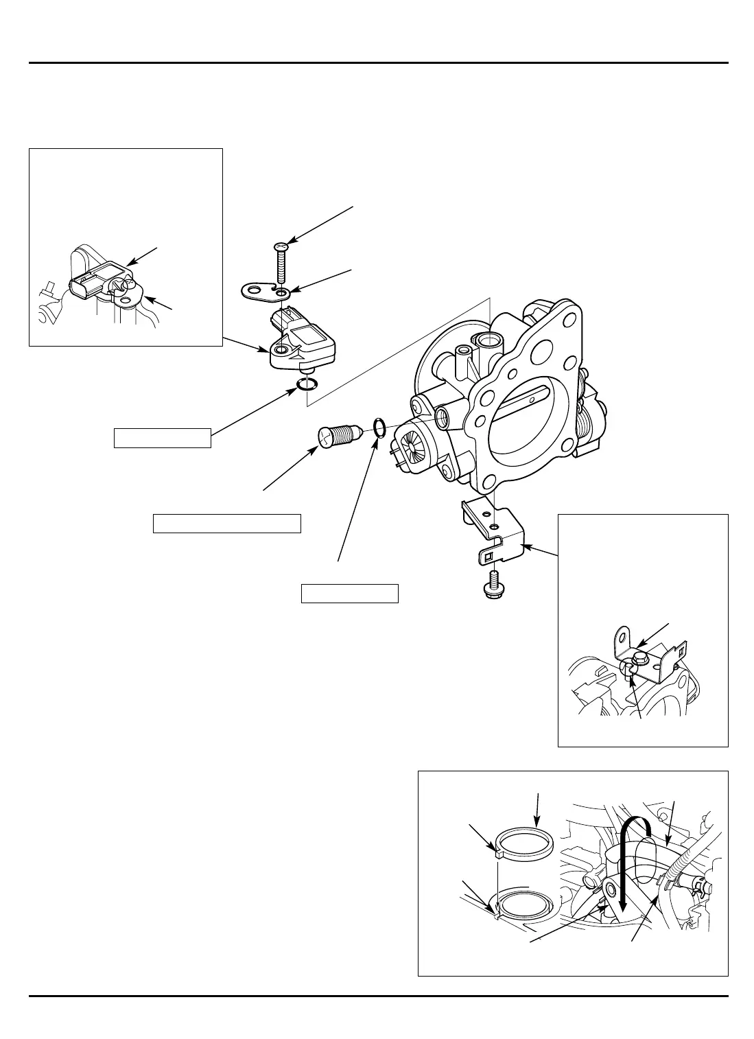
d. THROTTLE BODY DISASSEMBLY/REASSEMBLY
BF135A•BF150A
5-132
e. INTAKE MANIFOLD INSTALLATION
1) Install the new intake manifold gasket on the intake manifold
assembly.
• Install aligning the projection on the gasket with the
groove in the intake manifold.
2) Install the intake manifold assembly on the engine.
• Take care not to pinch the pressure regulator return hose
and the air vent tube at the top of the intake manifold.
[2]
5 x 18 mm SCREW
[2] INTAKE MANIFOLD GASKET
[5]
TOP OF INTAKE
MANIFOLD
[4]
PRESSURE REGULATOR
RETURN HOSE
[3]
AIR VENT TUBE
[1]
PROJECTION
[6]
GROOVE
[5] O-RING
Do not reuse.
[6] IDLE ADJUSTING SCREW
ADJUSTMENT: P. 5-93
[3]
SET PLATE
[1] MAP SENSOR
ASSEMBLY:
Apply the engine oil to the new
O-ring and install it on the MAP
sensor. Install aligning the
cutout in the set plate with the
lib of the sensor as shown.
[1]-1
MAP
SENSOR
[1]-2
SET
PLATE
[4]
HARNESS CLIP BRACKET E
ASSEMBLY:
Install the bracket aligning
the cutout in the bracket
with the stopper pin.
[4]-1
HARNESS CLIP
BRACKET E
[4]-2 STOPPER PIN
[5] O-RING
Do not reuse.




 To Next Page