8-4
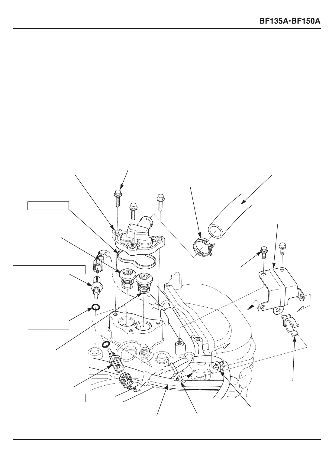
d. ASSEMBLY
1) Check the thermostats for the identification mark and install each of them in the proper position (P. 8-3).
Install the thermostat for the cylinder head in the ECT sensor 2 installation hole side, and install the thermostat for
the cylinder block in the ECTsensor 4 installation hole side.
2) Install a new thermostat cover O-ring on the thermostat cover, and tighten the thermostat cover with the three 6 x 22
mm flange bolts securely.
3) Set the tube clamp D25.0 on the water relief tube A, and insert the water relief tube A into the thermostat cover
securely.
4) Position the tube clamp D25.0 so that its lugs are toward the direction shown.
5) Install a new 9.5 x 1.9 mm O-ring on the ECT sensor 2 and 4 respectively. Apply a liquid sealant (ThreeBond
®
#1201
or #1215 or equivalent) to the threads and seat of each sensor.
6) Install the ECT sensor 2 and 4, and tighten them to the specified torque.
TORQUE: 12 N
.
m (1.2 kgf
.
m, 9 lbf
.
ft)
7) Set the 18.5 mm clamp, harness band clip and the wire harness clip on the harness clip bracket B, and tighten the
two 6 x 14 mm flange bolts.
8) Install the engine cover (P. 4-2).
[7]
WIRE HARNESS CLIP
[6]
HARNESS BAND CLIP
6 x 14 (2)
6 x 22 (3)
[8]
BREATHER TUBE
[5]
18.5 mm CLAMP
[4]
HARNESS CLIP
BRACKET B
[10]
THERMOSTAT
(50˚C: For cylinder head)
[13]
THERMOSTAT
(60˚C: For cylinder block)
[1]
THERMOSTAT COVER
[3]
WATER RELIEF TUBE A
[2]
TUBE CLAMP D25.0
[9]
ECT SENSOR 2
12 N
.
m (1.2 kgf
.
m, 9 lbf
.
ft)
[14]
THERMOSTAT
COVER O-RING
Do not reuse.
[12]
ECT SENSOR 4
12 N
.
m (1.2 kgf
.
m, 9 lbf
.
ft)
[11]
9.5 x 1.9 mm
O-RING (2)
Do not reuse.
 Loading...