8-9
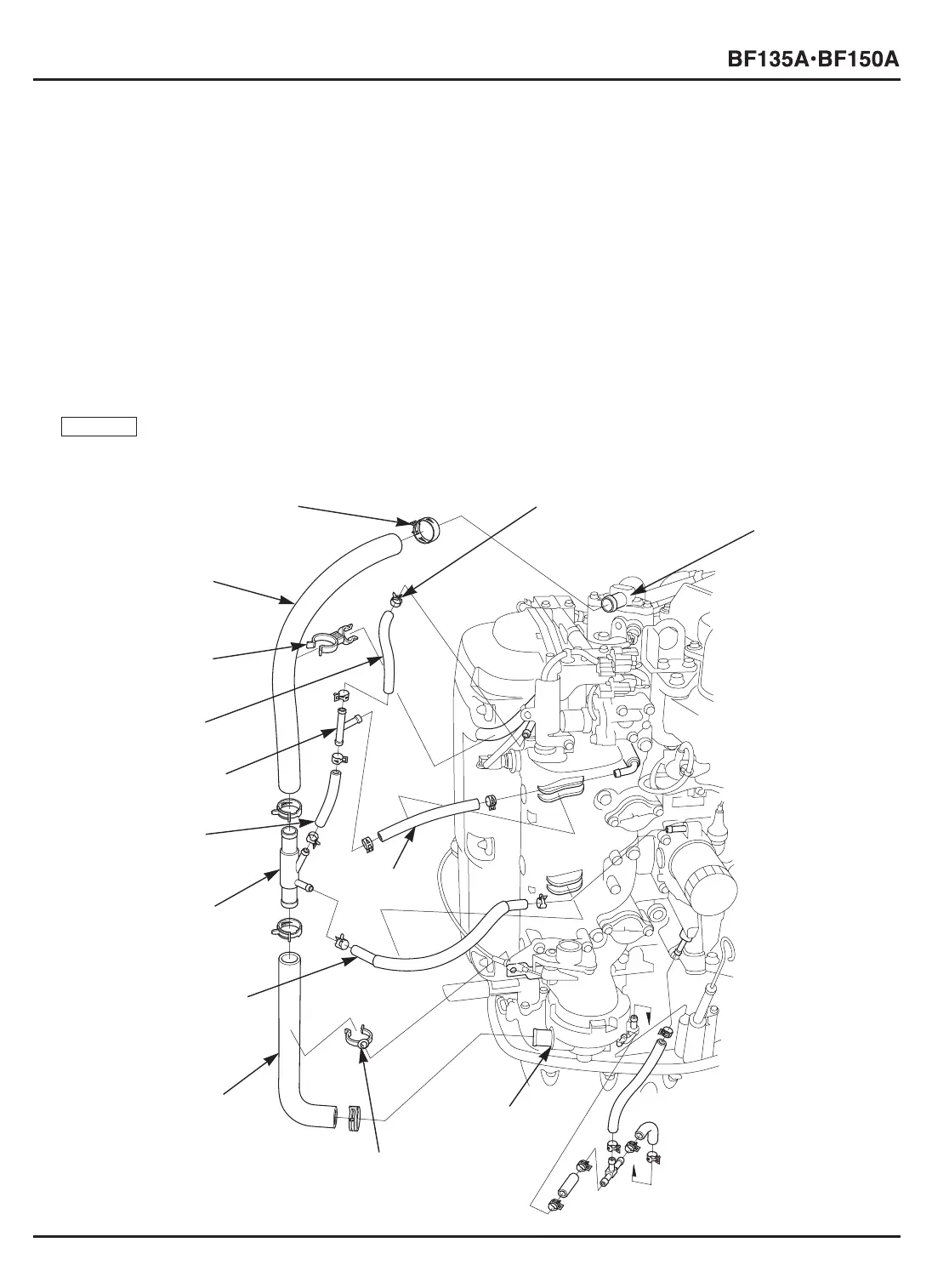
6) Connect the 7 x 75 mm tube and the water tube E to the 4-way joint.
7) Connect the 7 x 75 mm tube to the fuel tube joint.
8) Connect the 7 x 90 mm tube and the 7 x 120 mm tube to the fuel tube joint.
9) Connect the 7 x 120 mm tube with the lugs of the tube clamp D10.5s toward down.
g. INSTALLATION OF WATER RELIEF TUBE ASSEMBLY
1) Connect the water relief tube B to the exhaust guide.
Clamp the water relief tube B with the water tube clamp B.
2) Connect the water relief tube A to the thermostat cover and set the tube clamp D25.0 with its lugs toward the direction
shown (i.e. toward the intake manifold side).
Clamp the water relief tube A and the main wire harness with the water tube clamp.
3) Connect the 7 x 90 mm tube and the water tube E to the engine side.
4) Connect the 7 x 120 mm tube to the engine side and set the tube clamp D10.5s with the lugs toward down.
5) Install the following parts.
– L./R. engine under covers (P. 4-14)
– Engine cover (P. 4-2)
Start the engine after connecting the tubes. Check that the
water does not leak from each joint.
NOTICE
[10]
7 x 75 mm TUBE
[11]
FUEL TUBE JOINT
[9]
4-WAY JOINT
[4]
EXHAUST GUIDE
[6]
WATER RELIEF TUBE B
[1]
TUBE CLAMP D25.0 (4)
[7]
WATER TUBE E
[8]
7 x 120 mm
TUBE
[12]
7 x 90 mm TUBE
[3]
THERMOSTAT
COVER
[14]
WATER RELIEF
TUBE A
[13]
WATER TUBE CLAMP
[5]
WATER TUBE CLAMP B
[2]
TUBE CLAMP D10.5 (8)




 To Next Page