18-29
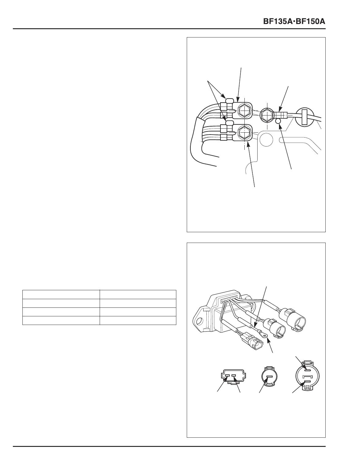
• FRAME GROUND
INSTALLATION:
Tighten the 6 x 12 mm flange bolts while pushing each ground
terminal against the projection on the crankcase as shown.
• POWER TILT RELAY GROUND CABLE
INSTALLATION:
1) Connect the Black, Blue, Green/White wire side of the
ground terminal to the upper connection, and the Green,
Green/Black, Blue, Black/White wire side of the ground
terminal to the lower connection as shown.
2) Tighten the 6 x 12 mm flange bolt while pushing each
frame ground terminal against the projection on the
crankcase.
[1]
PROJECTIONS
[4]
PROJECTION
[1]
GROUND WIRE
Bl
Lb
Lg
W
G
Bu
[2]
FRAME GROUND
TERMINAL
[3]
POWER TILT RELAY
GROUND TERMINAL
[5]
FRAME GROUND
TERMINAL
Green to Black terminals Continuity
Blue to Black terminals Continuity
Green to White terminals No continuity
Blue to White terminals No continuity
b. INSPECTION
• POWER TILT RELAY
Note that the power tilt relay inspection must be made on
single unit of the power tilt relay.
1) Check for continuity between the terminals.












 To Next Page