11 Safety Bus Manual — P/N LS10177-000HI-E:B 02/21/2019
Section 2: Introduction
The Safety Bus system makes it possible to carry out gas and fire detection functions as well as
extinguishing/release functions on a single bus, guaranteeing high safety levels. The system con-
sists of one or two control boards inserted in the H-S81-HS series panels, and a number, varying
from 1 to 64, of addressed field modules.
The system consists of the following components:
2.1 Principles of Operation
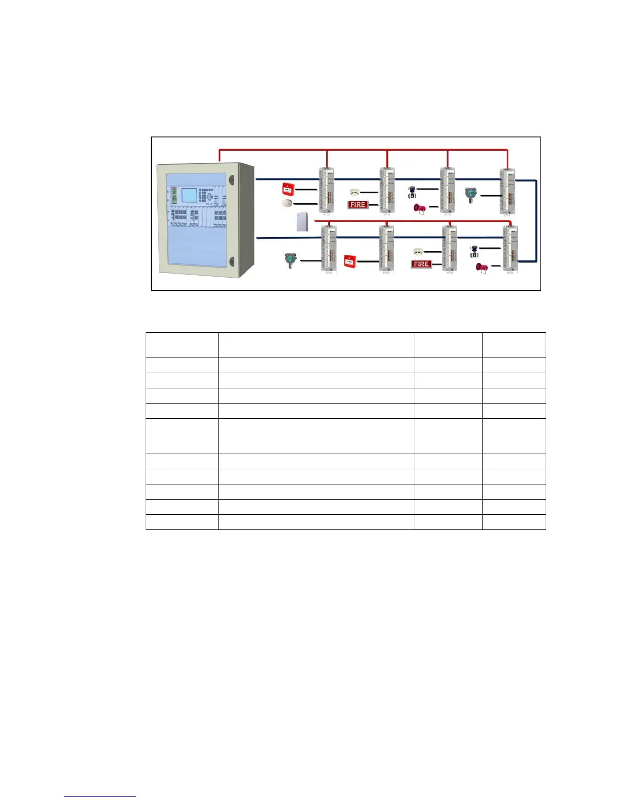
Communication between the control board and the addressed modules is based on CAN (Controller
Area Network) protocol with ring architecture to guarantee maximum operation even in the event
of a single failure. All the field modules are connected to the control panel forming a ring. Each
module connected to the communication ring is assigned a unique address by the SB-PRG pro-
grammer. All module operating parameters are set by the Pro-HS81 panel configuration program.
During standard operation, the control board checks the communication integrity of the ring by
monitoring the state of the I/O modules present along the ring. All changes in the state of the I/O
module channels are sent from the module to the control board. All failures concerning the modules
and the communication ring are displayed on the control panel monitor. The table below lists the
module failure types displayed on the control panel:
Part Number Description Input channels
Output
channels
H-S81-HS H-S81-HS series panel * *
S81-F7011-1 Safety Bus (mono/duplex) control board * *
CCT8 Termination cable for S81-F7011-1 boards
SB-SIM Supervised input modules 8 supervised *
SB-SIM-GM Supervised input modules with earth leakage monitor
Note: One (1) SB-SIM-GM is required per power supply for ground fault
supervision
8 supervised *
SB-AIM 4-20mA analog input module 8 4-20mA analog *
SB-SCM Solenoid valve output control module * 8 supervised
SB-NCM Notification Appliances output control module * 8 supervised
SB-ECM Extinguishing/Release system I/O module 8 supervised 4 supervised
SB-PRG SB module programmer * *
Table 2.1 List of Safety Bus System Components
Figure 2.1 Safety Bus system
 Loading...


