Safety Bus Manual — P/N LS10177-000HI-E:B 02/21/2019 54
Wiring the I/Os Installation
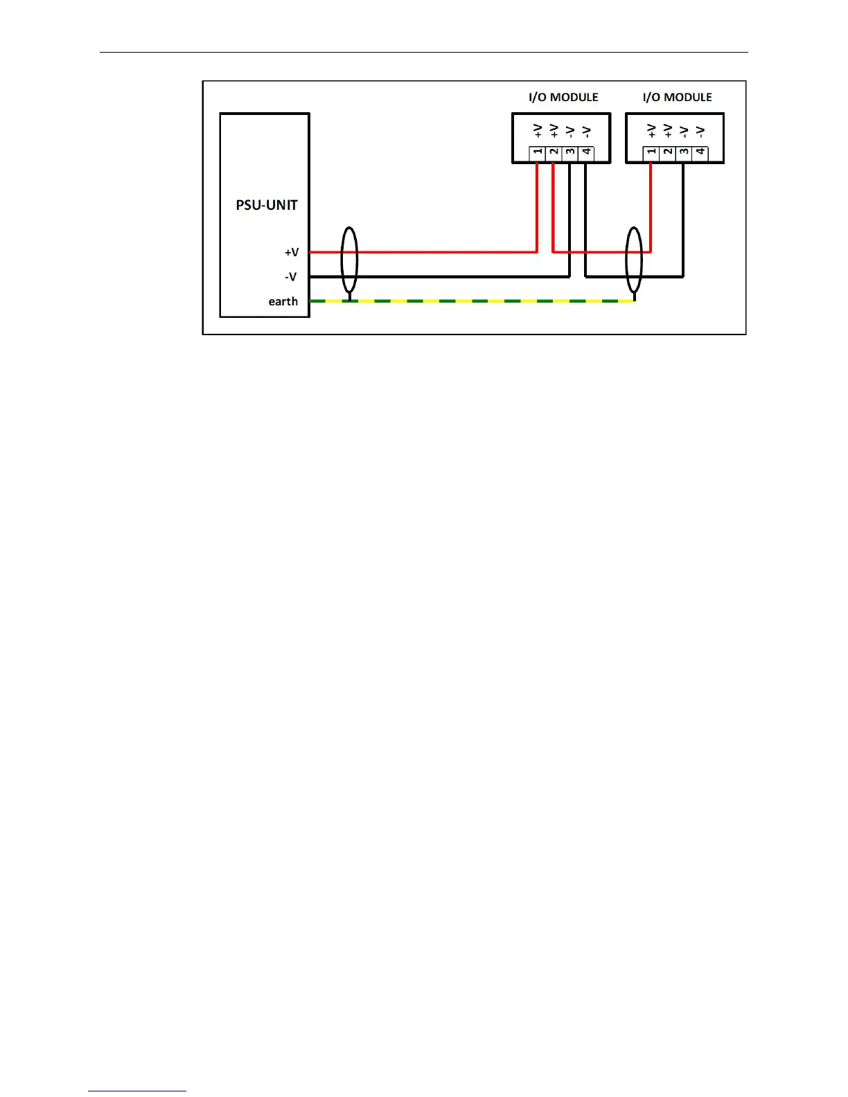
4.3 Wiring the I/Os
For wiring the I/Os, it is advisable use a screened wire with a minimum section of 1.5mm². The
sensor and actuator wires must be separated from the AC power supply cables and placed at a suffi-
cient distance from interfering devices such as motors, drives and transformers. The screened cable
braiding must be connected to the ground bar located in the box that houses the modules.
4.4 Putting Into Service
Before putting into service, disconnect the outputs that control extinguishing systems to avoid the
accidental release of the extinguishing agent.
4.5 Preliminary Checks
Before powering the system, do as follows:
1. Make sure that all connections have been made correctly.
2. Using an ohmmeter, make sure that all input and output lines are correctly terminated.
3. Make sure that the input and output cable screens are grounded in the metal box and they are
not grounded anywhere else.
4. Using an ohmmeter, make sure that there are no short-circuited lines or grounded cables.
4.6 Checking the Communication Ring
Before powering the system, use an ohmmeter to measure the resistance at the end of terminals –
LK1/+LK1 on all the modules present along the ring and make sure that the value is included
between 60 and 75 ohm. Also make sure that between terminals –LK1 and SLK1 and terminals
+LK1 and SLK1 there is a resistance >3 Mohm.
4.6.1 Checking the Installed Modules
At this point, power the system, wait for the control panel initialization cycle to complete and go to
the “Devices Verify” diagnostic menu of the control board. On this screen it is possible the follow-
ing real-time information for each of the modules forming the ring:
• Type of module programmed
• Type of modules detected
• Address of the module connected to Link1 (upstream module)
• Address of the module connected to Link2 (downstream module)
Figure 4.3 Typical Series Connections
 Loading...


