Safety Bus Manual — P/N LS10177-000HI-E:B 02/21/2019 26
SB-SIM/GM Module System Components
Terminal Block TB3
This terminal block is used to connect channels 1, 2, 3, and 4.
Terminal Block TB4
This terminal block is used to connect channels 5, 6, 7, and 8.
Grounding the Module
The module must be connected to the system ground using the screw located on the front panel.
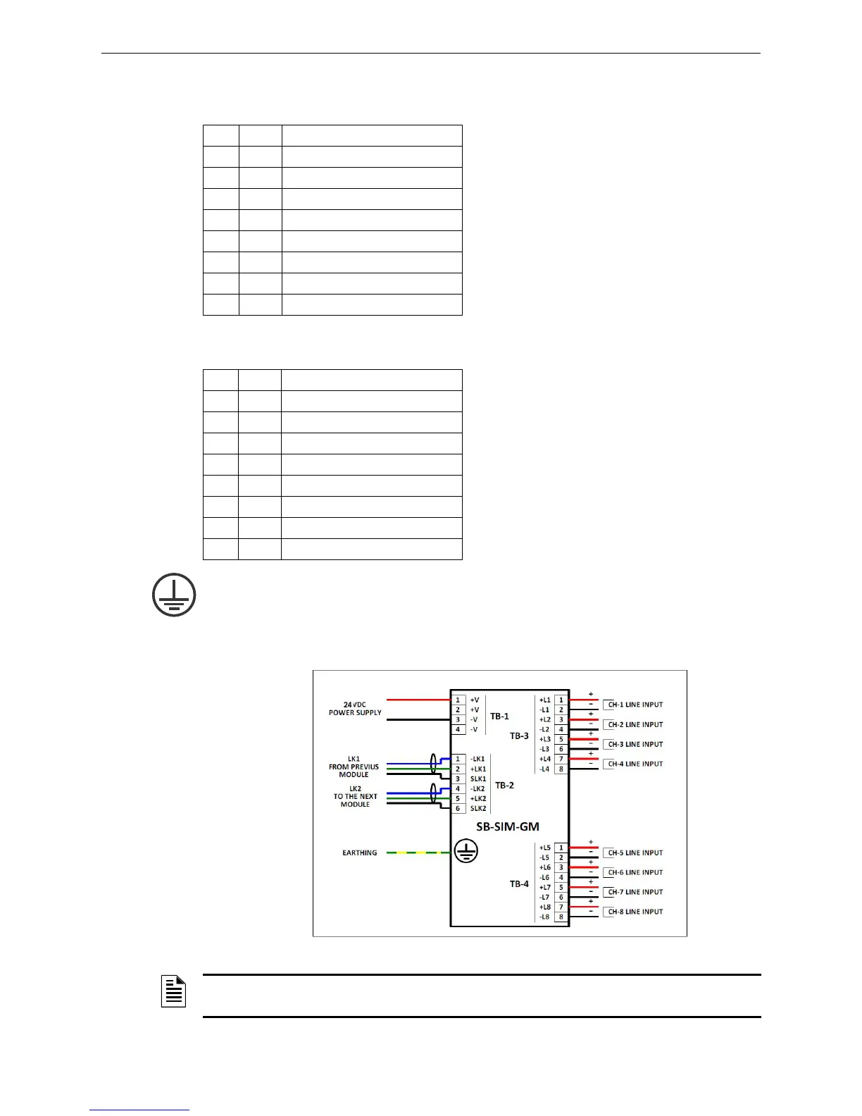
3.3.4 Typical Connections
Pin Tag Function
1 +L1 CH-1 line input positive
2 -L1 CH-1 line input negative
3 +L2 CH-2 line input positive
4 -L2 CH-2 line input negative
5 +L3 CH-3 line input positive
6 -L3 CH-3 line input negative
7 +L4 CH-4 line input positive
8 -L4 CH-4 line input negative
Pin Tag Function
1 +L5 CH-5 line input positive
2 -L5 CH-5 line input negative
3 +L6 CH-6 line input positive
4 -L6 CH-6 line input negative
5 +L7 CH-7 line input positive
6 -L7 CH-7 line input negative
7 +L8 CH-8 line input positive
8 -L8 CH-8 line input negative
Figure 3.3 SB-SIM-GM Module Connections
NOTE: A maximum of 32 detectors and/or alarm buttons can be connected to each conventional
detection line.
 Loading...


