Safety Bus Manual — P/N LS10177-000HI-E:B 02/21/2019 38
SB-ECM Module System Components
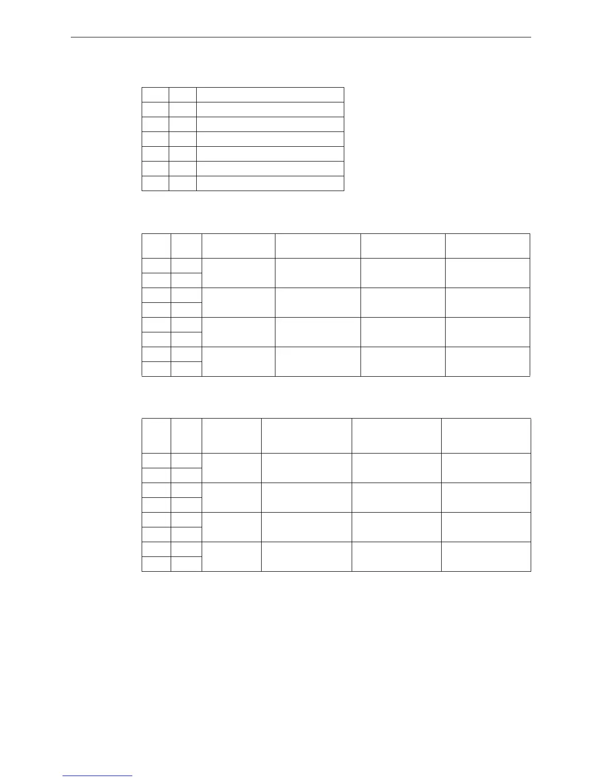
Terminal Block TB2
This terminal block connects the two ring communication links.
Terminal Block TB3
This terminal block is used to connect Input channels 1, 2, 3, and 4.
Terminal Block TB4
This terminal block is used to connect Input channels 5, 6, 7, and 8.
Pin Tag Function
1 -LK1 Link-1 Negative
2 +LK1 Link-1 Positive
3 SLK1 Link-1 Screen
4 -LK2 Link-2 Negative
5 +LK2 Link-2 Positive
6 SLK2 Link-2 Screen
Pin Tag
I/O Mode
Operating mode
Embedded Mode 1
Operating mode
Embedded Mode 2
Operating mode
Embedded Mode 3
Operating mode
1 +L1
Ch-1 line input Manual Discharge Manual Discharge
Main Automatic
Discharge
2 -L1
3 +L2
Ch-2 line input
Sequence Stop
(Hold)
Sequence Stop
(Hold)
Sequence Stop
(Hold)
4 -L2
5 +L3
Ch-3 line input
Discharge Inhibition
(Inhibit/Abort)
Discharge Inhibition
(Inhibit/Abort)
Discharge Inhibition
(Inhibit/Abort)
6 -L3
7 +L4
Ch-4 line input
Automatic Disabled
AUT-OFF
Automatic Disabled
AUT-OFF
Automatic Disabled
AUT-OFF
8 -L4
Pin Tag
I/O Mode
Operating
mode
Embedded Mode 1
Operating mode
Embedded Mode 2
Operating mode
Embedded Mode 3
Operating mode
1 +L5
Ch-5 line input
Low Cylinder Pressure
(PSL)
Main/Reserve
Secondary Manual
Discharge
2 -L5
3 +L6
Ch-6 line input
System Tripped
(PSH)
System Tripped
(PSH)
System Tripped
(PSH)
4 -L6
5 +L7
Ch-7 line input
Input for Automatic
Extinguishing/release #1
Input for Automatic
Extinguishing/release #1
Input for Automatic
Extinguishing/release #1
6 -L7
7 +L8
Ch-8 line input
Input for Automatic
Extinguishing/release #2
Input for Automatic
Extinguishing/release #2
Input for Automatic
Extinguishing/release #2
8 -L8
 Loading...


