37 Safety Bus Manual — P/N LS10177-000HI-E:B 02/21/2019
System Components SB-ECM Module
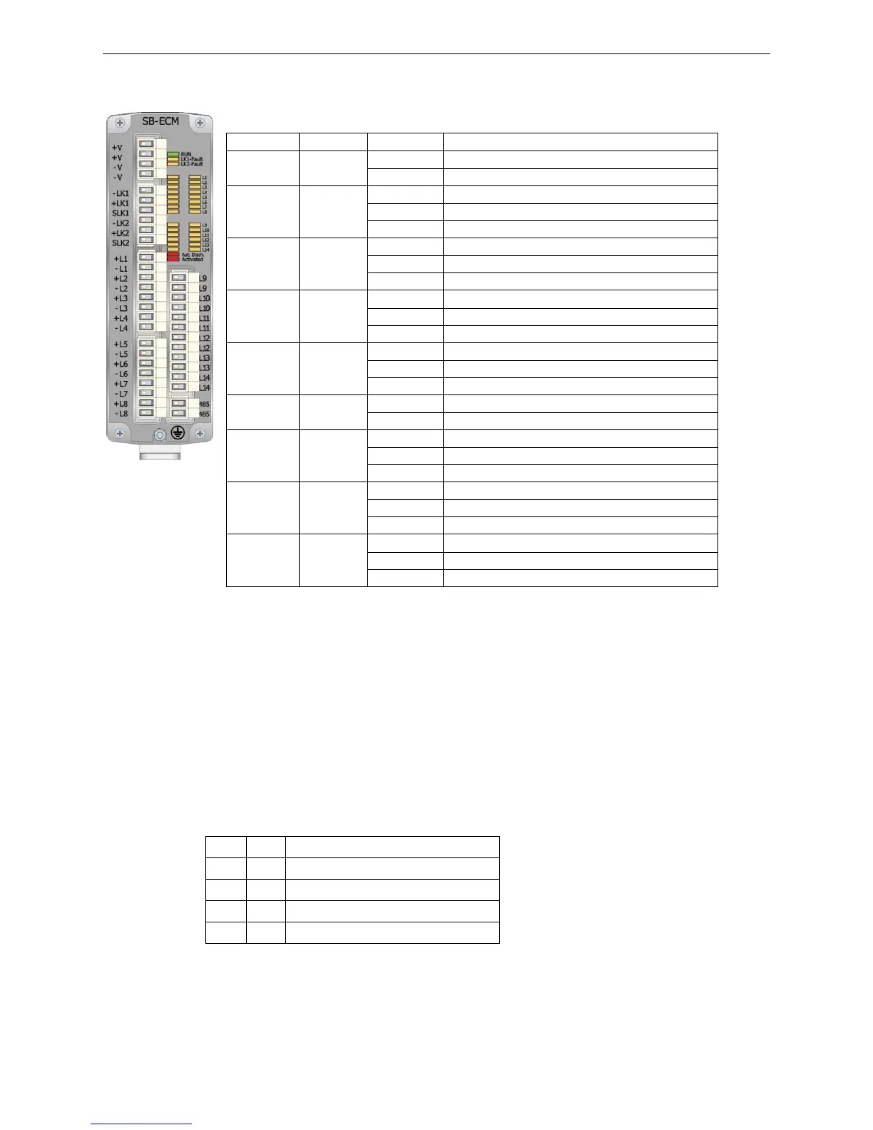
3.7.2 Visual Indicators
The front panel of the module features 36 LEDs that indicate the following conditions:
3.7.3 Connections
The SB-ECM module features the following connectors:
Terminal Block TB1
This terminal block supplies power to the module.
Tag Color
M
Mode Condition
RUN Green
O
On Solid Normal operation
1
1 During the startup sequence, all the LEDs except for the green RUN LED
blink 3 times, then the seven red LEDs L1-L7 will go on for 2 seconds to
indicate the module address in binary format (L1=1, L2=2, L3=4, L4=8,
L5=16, L6=32, L7=64). At this point, the fourteen yellow LEDs L1-L14 will
begin to blink rapidly until the module is configured by the panel.
Off Module failure or no power
LK1-Fault Yellow
O
Off Communication on Link LK1 present
Blinking Link LK1 towards board interrupted
On Solid Communication failure on Link LK1
LK2-Fault Yellow
O
Off Communication on Link LK2 present
Blinking Link LK2 towards board interrupted
On Solid Communication failure on Link LK2
L1-L8 Red
O
Off Channel in normal state
2
2 Embedded mode - the red LED L3, indicating the status of the inhibit input,
blinks during the discharge sequence inhibition time.
Blinking Channel in pre-alarm
On Solid Channel in alarm
L1-L8 Yellow
O
Off Channel in normal state
Blinking Channel fault (module or line)
On Solid Channel disabled
L9-L14 Red
O
Off Channel inactive
On Solid Channel active
L9-L14 Yellow
O
Off Channel in normal state
Blinking Channel fault (module or line)
On Solid Channel disabled
V15 Red
O
On Solid V15 variable (automatic discharge) active
Blinking Discharge sequence startup (active)
Off V15 variable (automatic discharge) inactive
Mode Green
O
Off I/O Mode
Blinking Internal logic in progress (only in I/O mode)
On Solid Embedded Mode
Pin Tag Function
1 +V 24VDC Power supply positive
2 +V 24VDC Power supply positive
3 -V 24VDC Power supply negative
4 -V 24VDC Power supply negative
 Loading...


