27 Safety Bus Manual — P/N LS10177-000HI-E:B 02/21/2019
System Components SB-AIM Module
3.4 SB-AIM Module
This module can control eight 4-20mA analog inputs with safety-related functions. All the channels
are continuously tested during operation. The following types of transducers can be connected to
this board: Explosive gas detectors, Toxic Gas Detectors , Oxygen sensors, Temperature Sen-
sors/detectors, Flame Detectors, 4-20mA generic Sensors/detectors. Each channel features dedi-
cated terminals to supply 24VDC power to field device.
3.4.1 Technical Specifications
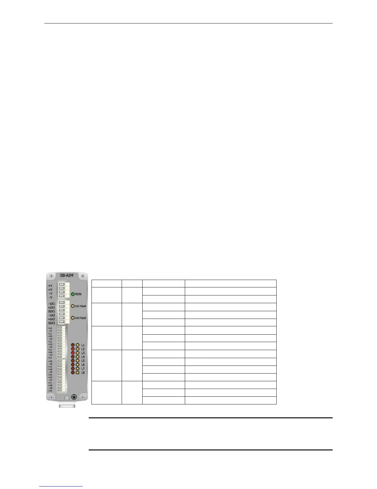
3.4.2 Visual Indicators
The front panel of the module features 19 LEDs that indicate the following conditions:
NOTE: During the startup sequence, the yellow and red LEDs blink 3 times, then the seven red
LEDs L1-L7 will go on for 2 seconds to indicate the module address in binary format (L1=1, L2=2,
L3=4, L4=8, L5=16, L6=32, L7=64). At this point, the eight yellow LEDs L1-L8 will begin to blink
rapidly until the module is configured by the panel.
• Number of input channels:
8 individually configurable
• Alarm threshold:
3 programmable thresholds
• Measuring range:
4-20mA
• Channel test:
continuous
• Max current for each power supply:
250mA individually protected by self-resetting fuse
• Power supply voltage:
24VDC
• Current consumption in stand by:
119mA
• Operating temperature:
0 to 49 °C (32 - 120.2 °F)
• Storage temperature:
-55 to 85 °C (-67 to 185°F)
• Max humidity:
0-95% non condensing
• Protection rating:
IP30
• Mounting:
T35 DIN rail
• Dimensions:
53 x 167 x 100 (W x H x D mm) (2.1” x 6.6” x 4”)
• Weight:
approx. 600g (21 oz.)
• Connections (power supply, Link):
2.5mm² removable terminal blocks
• Connections (analog inputs):
1.5mm² removable terminal blocks
• Max. Line impedance:
20 ft (6.096 m) in same room, in conduit
• Max. Line Impedance Input Channels 1-8:
50 ohms
• Ground Fault impedance:
</ 500 ohms
• Max distance between two modules:
20 ft (6.096 m) in conduit
Tag Color Mode Condition
RUN Green
On Solid Normal operation
Off Module failure or no power
LK1-Fault Yellow
Off Communication on Link LK1 present
Blinking Link LK1 towards board interrupted
On Solid Communication failure on Link LK1
LK2-Fault Yellow
Off Communication on Link LK2 present
Blinking Link LK2 towards board interrupted
On Solid Communication failure on Link LK2
L1-L8 Red
Off Channel in normal state
Blinking 1 sec. Channel in Level-1 alarm
Blinking 0.5 sec. Channel in Level-2 alarm
On Solid Channel in Level-3 alarm
L1-L8 Yellow
Off Channel in normal state
Blinking Channel fault (module or line)
On Solid Channel disabled
 Loading...


