55 Safety Bus Manual — P/N LS10177-000HI-E:B 02/21/2019
Installation Checking the Communication Ring
The lines marked with the * symbol indicate a discrepancy between the module programmed in the
panel configuration program and the field module detected by the control board.
From this menu it is also possible to check the entire communication ring and easily identify any
installation and/or programming errors.
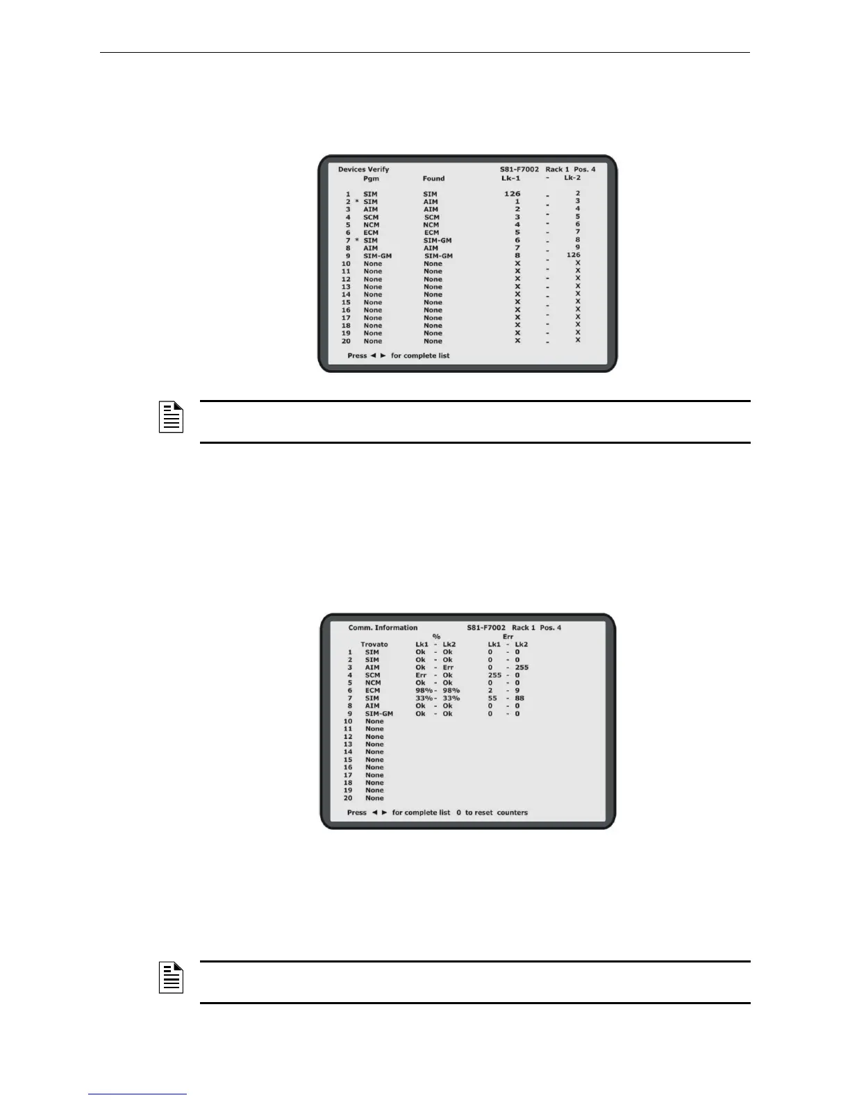
4.6.2 Checking the Communication Links
After making sure that all the modules installed are the correct ones, it is necessary to check the
quality of all the links that form the communication ring. This information is available in the
“Comm. Information” diagnostic menu of the control board. For each of the two links of every
module present on the ring it is possible to see:
• The link status (err = No Link , OK = Link present, 1-99% link quality)
• The error counter (0-255)
Press “0” to reset the error counter. The quality of a link should always be 100%, which corre-
sponds to OK. In some unfavorable conditions, for link segments that exceed the max allowed
value or link segments subject to electromagnetic disturbance, this value could be slightly lower but
must never go below 97%. The error counters for each link indicate the number of errors detected
by each module since the last power on.
Figure 4.4 Verify Devices Screen
NOTE: Address 126 indicates the Master control board, while address 127 indicates the Slave
control board.
Figure 4.5 Comm. Information Screen
NOTE: Reset the error counters before performing a diagnosis on the quality of the
communication link.
 Loading...


