35 Safety Bus Manual — P/N LS10177-000HI-E:B 02/21/2019
System Components SB-NCM Module
Grounding the Module
The module must be connected to the system ground using the screw located on the front panel.
3.6.4 Typical Connections
6 -L7 CH-7 line input negative
7 +L8 CH-8 line input positive
8 -L8 CH-8 line input negative
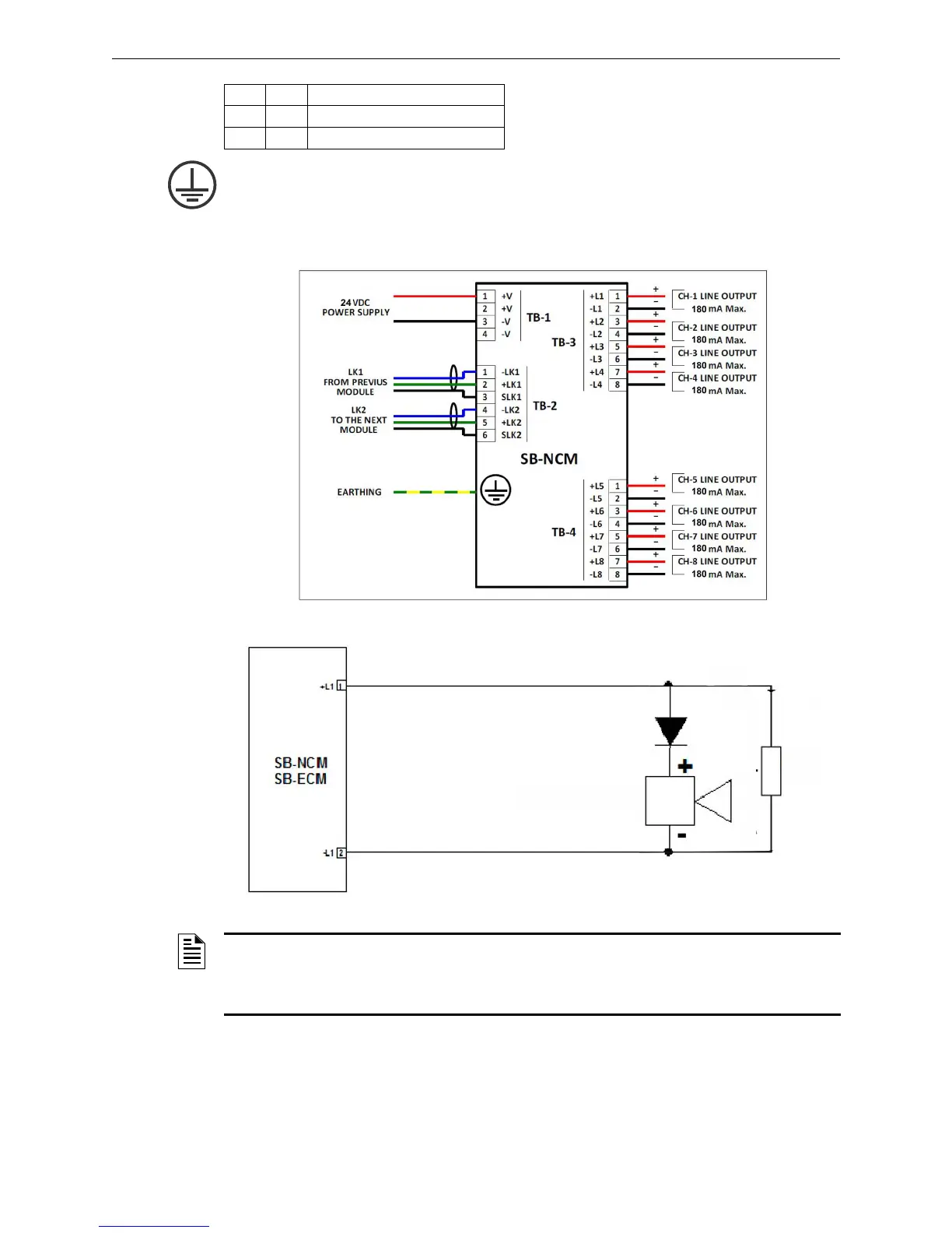
Figure 3.7 SB-NCM Module Connections
Figure 3.8 Typical Visual/Acoustic Signal Connections
NOTE: The SB-NCM module active outputs, when configured in fail-safe mode, are deactivated
when there is:
- no communication with the control board for 1 minute
- no communication between the control board and the panel for 5 minutes
 Loading...


