31 Safety Bus Manual — P/N LS10177-000HI-E:B 02/21/2019
System Components SB-SCM Module
3.5.3 Connections
The SB-SCM module features the following connectors:
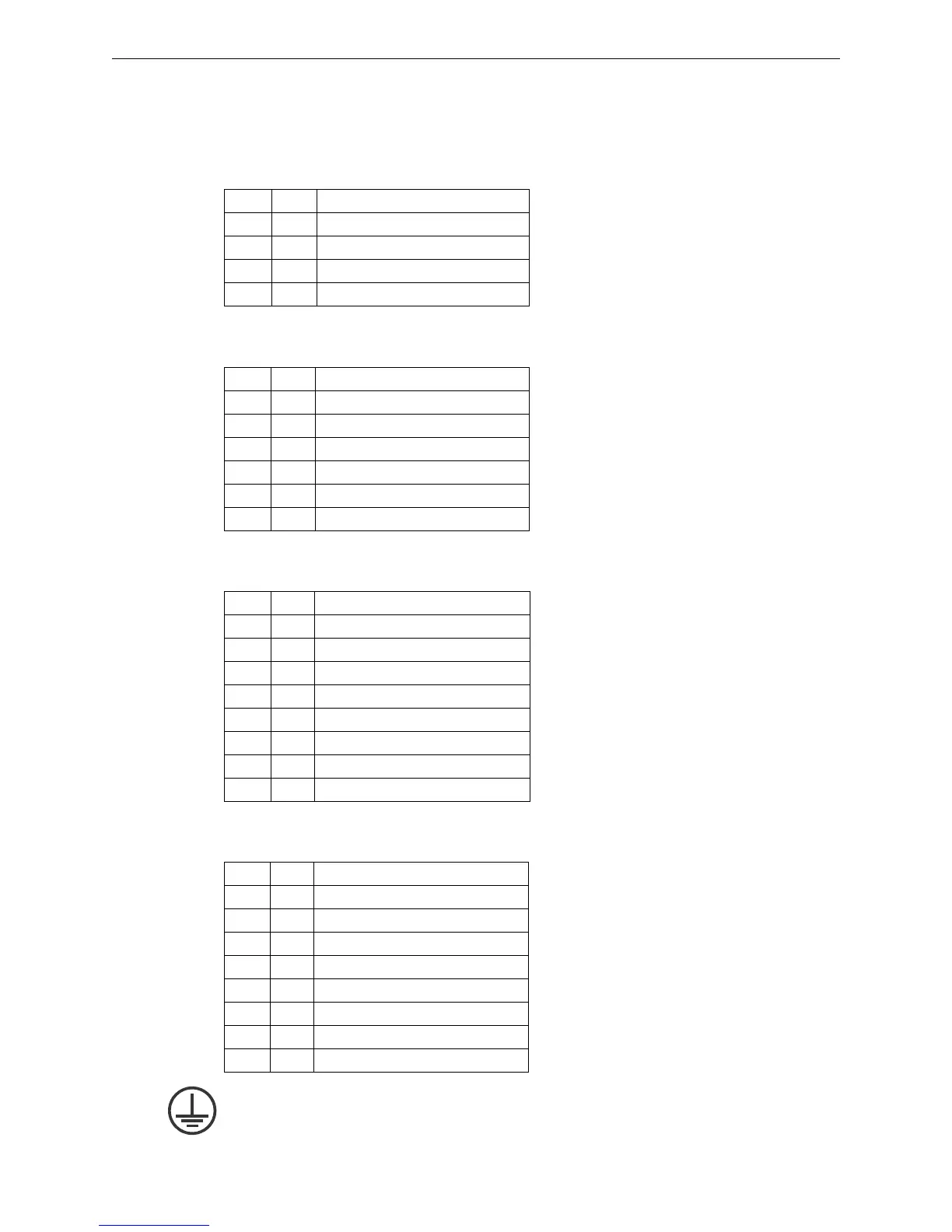
Terminal Block TB1
This terminal block supplies power to the module.
Terminal Block TB2
This terminal block connects the two ring communication links.
Terminal Block TB3
This terminal block is used to connect channels 1, 2, 3, and 4.
Terminal Block TB4
This terminal block is used to connect channels 5, 6, 7, and 8.
Grounding the Module
The module must be connected to the system ground using the screw located on the front panel.
Pin Tag Function
1 +V 24VDC Power supply positive
2 +V 24VDC Power supply positive
3 -V 24VDC Power supply negative
4 -V 24VDC Power supply negative
Pin Tag Function
1 -LK1 Link-1 Negative
2 +LK1 Link-1 Positive
3 SLK1 Link-1 Screen
4 -LK2 Link-2 Negative
5 +LK2 Link-2 Positive
6 SLK2 Link-2 Screen
Pin Tag Function
1 +L1 CH-1 line output positive
2 -L1 CH-1 line output negative
3 +L2 CH-2 line output positive
4 -L2 CH-2 line output negative
5 +L3 CH-3 line output positive
6 -L3 CH-3 line output negative
7 +L4 CH-4 line output positive
8 -L4 CH-4 line output negative
Pin Tag Function
1 +L5 CH-5 line output positive
2 -L5 CH-5 line output negative
3 +L6 CH-6 line output positive
4 -L6 CH-6 line output negative
5 +L7 CH-7 line output positive
6 -L7 CH-7 line output negative
7 +L8 CH-8 line output positive
8 -L8 CH-8 line output negative
 Loading...


