Safety Bus Manual — P/N LS10177-000HI-E:B 02/21/2019 50
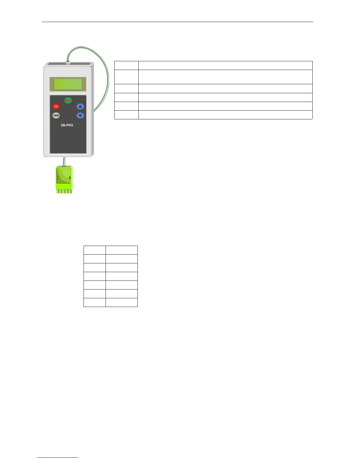
SB-PRG Programmer System Components
3.8.2 Visual Indications
The front panel features an alphanumeric display and five buttons that carry out the
following functions:
DISPLAY INDICATIONS:
Err = Module not connected or failure
LOBAT = Battery needs replacing
001 – 064 = Module address
3.8.3 Connections
The SB-PROG programmer features the following connectors:
Terminal Block TB1
This connector must be connected to terminal block TB2 of the module to program.
Module Programming Procedure
To program the modules, carry out the following steps in order:
1. Power the module to program.
2. Connect the programmer’s TB1 terminal block to the module’s TB2 terminal block.
3. Press ON to turn on the programmer.
4. Set the desired address using the ↑ ↓ keys on the programmer.
5. Press PROG to program the module address.
6. Press VER to verify the address programmed into the module.
7. Disconnect the programmer.
8. Apply an adhesive label with the address in the space provided on the module front panel.
Key Function
ON Used to power on the device. The programmer will power off automatically after
being idle for 30 seconds
VER Reads the address set in the module and checks its operation
↑ Increases the address to program. The range is limited to the allowed addresses
↓ Decreases the address to program. The range is limited to the allowed addresses
PRG Programs the selected address in the Module flash memory
Pin Signal Name
1 +Link-1
2 -Link-1
3 Link-1 Screen
4 NU
5 NU
6 NU
 Loading...


