29 Safety Bus Manual — P/N LS10177-000HI-E:B 02/21/2019
System Components SB-AIM Module
Terminal Block TB4
This terminal block is used to connect analog channels L5, L6, L7, and L8.
Grounding the Module
The module must be connected to the system ground using the screw located on the front panel.
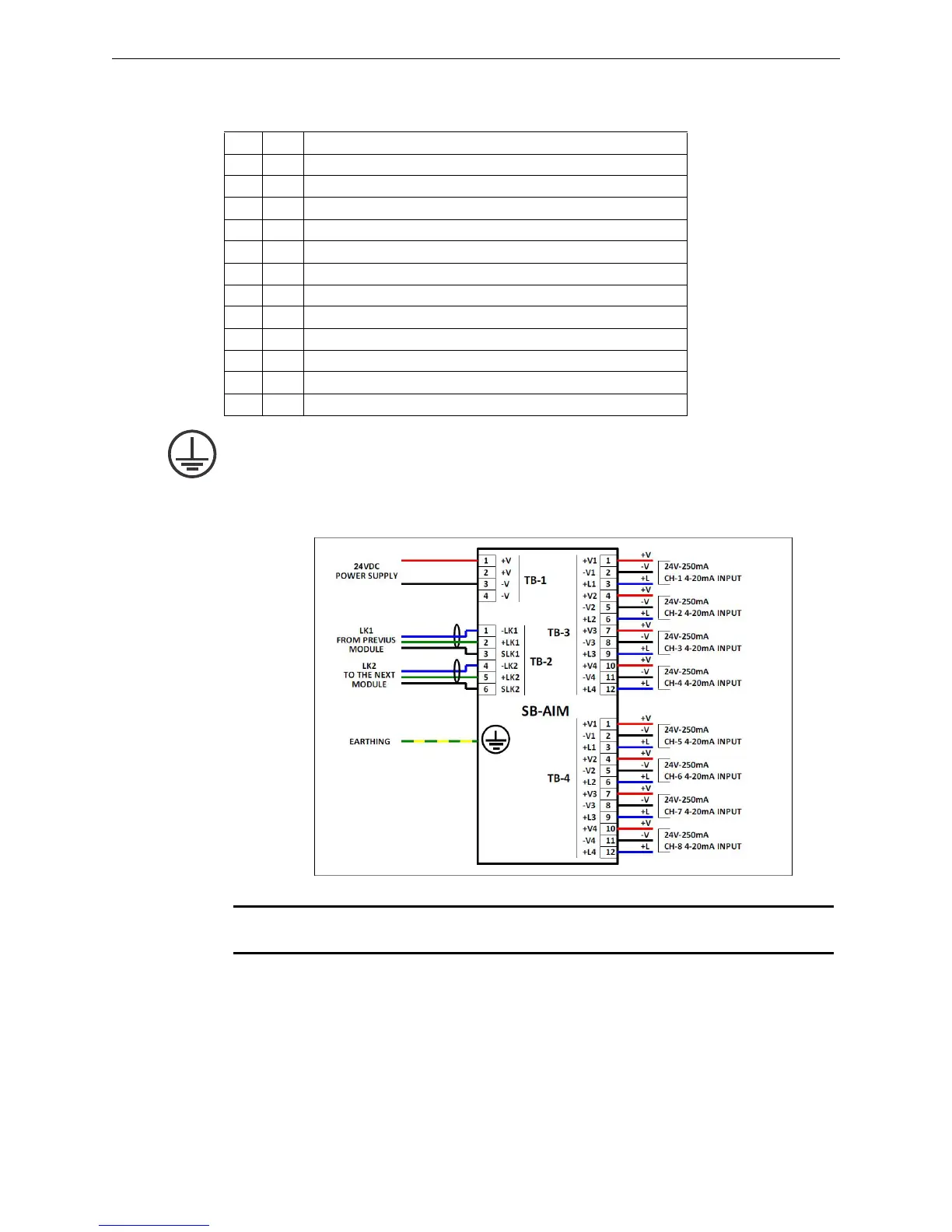
3.4.4 Typical Connections
Pin Tag Function
1 +V5 Ch-5 positive power supply (250mA max.) to field device
2 -V5 Ch-5 negative power supply (8250mA max.) to field device
3 +L5 Ch-5 4-20mA input
4 +V6 Ch-6 positive power supply (250mA max.) to field device
5 -V6 Ch-6 negative power supply (8250mA max.) to field device
6 +L6 Ch-6 4-20mA input
7 +V7 Ch-7 positive power supply (250mA max.) to field device
8 -V7 Ch-7 negative power supply (8250mA max.) to field device
9 +L7 Ch-7 4-20mA input
10 +V8 Ch-8 positive power supply (250mA max.) to field device
11 -V8 Ch-8 negative power supply (8250mA max.) to field device
12 +L8 Ch-8 4-20mA input
Figure 3.4 SB-AIM Module Connections
NOTE: If HVAC loss occurs resulting in the ambient temperature to rise above 40°C (104° F),
derate the 250 mA load to 230 mA per channel.
 Loading...


