33 Safety Bus Manual — P/N LS10177-000HI-E:B 02/21/2019
System Components SB-NCM Module
3.6 SB-NCM Module
This module can control eight 250mA outputs for controlling notification appliances (visual/acous-
tic signals). The current of the 8 outputs is limited by self-resetting fuses. Line control is carried out
by inverting the polarity. This also makes it possible to control electronic devices having low Cur-
rent consumption in stand by.
Notes:
Line control occurs only when the outputs are inactive.
Synchronization of devices between zones or within a zone is not permissible using this module.
3.6.1 Technical Specifications
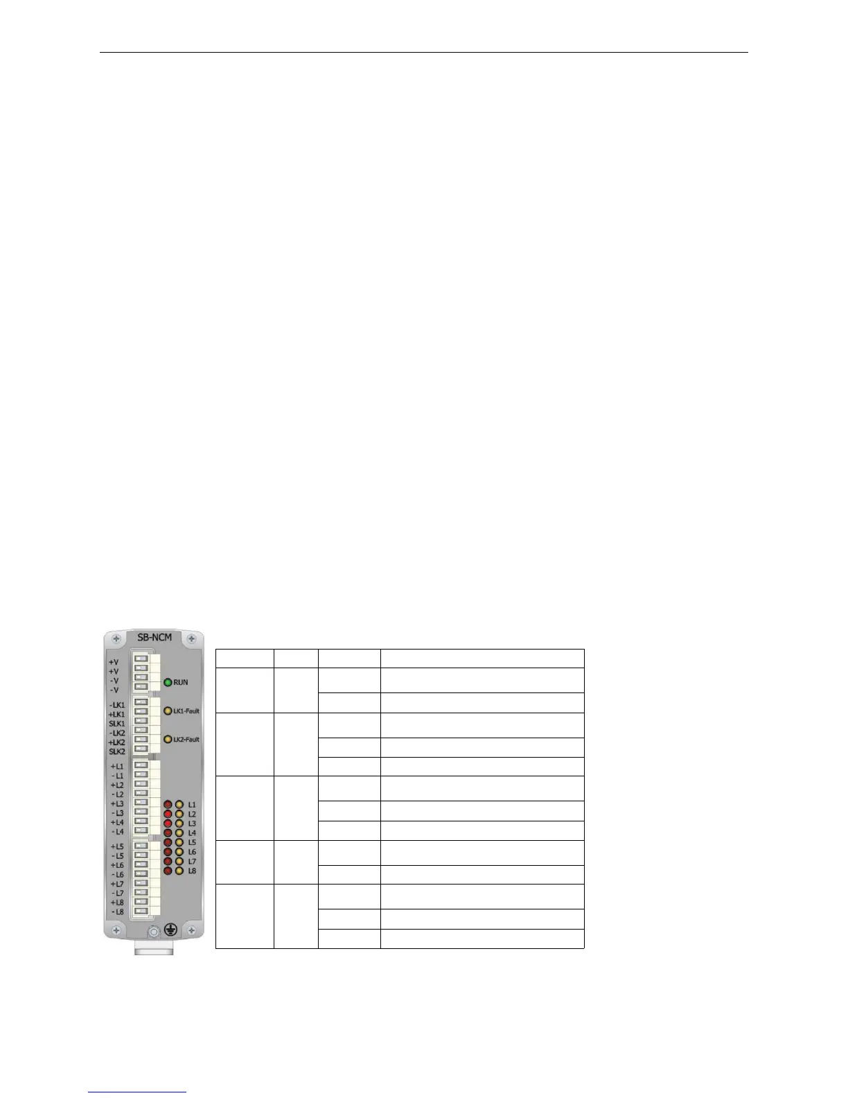
3.6.2 Visual Indicators
The front panel of the module features 19 LEDs that indicate the following conditions:
• Wiring: Class B Style Y
• Max channel current: 180 mA
• Fuse trip current: >600 mA
• Power supply voltage: 24VDC
• Current consumption in standby: 88mA
• Operating temperature:
0 to 49 °C (32 to 120.2 °F)
• Storage temperature:
-55 to 85 °C (-67 to 185°F)
• Max humidity: 0-95% non condensing
• Protection rating: IP30
• Mounting: T35 DIN rail
• Dimensions:
53 x 167 x 100 (W x H x D mm) (2.1” x 6.6” x 4”)
• Weight: approx. 600g (21 oz.)
• Connections: 2.5mm² removable terminal blocks
• Max. Line Impedance: 20 ft. (6.096 m) in the same room, in conduit
• Max. Line Impedance Output Ch.: 50 ohms
• Ground Fault Impedance: </ 500 ohms
• Max distance between two modules: 20 ft (6.096 m) in conduit
Tag Color Mode Condition
RUN Green
O
On Solid Normal operation
Off Module failure or no power
LK1-Fault Yellow
O
Off Communication on Link LK1 present
Blinking Link LK1 towards board interrupted
On Solid Communication failure on Link LK1
LK2-Fault Yellow
O
Off Communication on Link LK2 present
Blinking Link LK2 towards board interrupted
On Solid Communication failure on Link LK2
L1-L8 Red
O
Off Channel inactive
On Solid Channel active
L1-L8 Yellow
O
Off Channel in normal state
Blinking Channel fault (module or line)
On Solid Channel disabled
 Loading...


